The price per foot includes the fiber itself, connectors, and basic installation factors, with main drivers being cable type, distance, and any required conduit or termination hardware. This article outlines cost expectations, price ranges, and practical savings. Fiber-optic cable materials typically cost $1 to $6 per linear foot, depending on fiber count and cable type. Commercial building installations with 100-200 network drops generally range from $15,000 to $30,000. Single-mode fiber costs less per foot than multimode fiber, but it requires more. Typically, per drop fiber cabling prices range from $250 – $1000 per drop depending on the type of fiber (OM2, OM3, OM4, or OM5), multi or single mode, PVC or plenum, average drop length, and also the number of fibers in each cable. This. Whether you need singlemode, armored, or indoor plenum, this guide gives you the exact cost per foot of fiber optic cable — including installation — so you can budget without guesswork. Data aggregated from Q1 2026 contractor invoices across Texas, Ohio, and North Carolina. The installation type you choose and the layout of your property determine the total labor and materials needed for your project. Cost for fiber cabling projects.
[PDF]
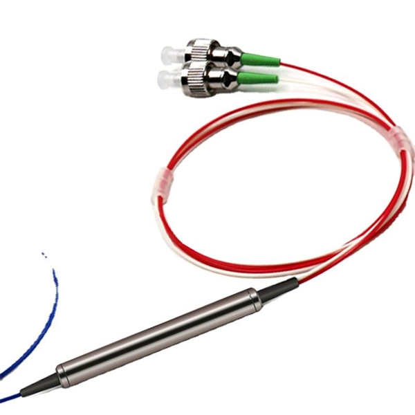
Abstract: Detecting partial discharges in cable joints is critical for timely defect identification and reliable transmission system operation. The electric field distribution of the optical fiber-implanted cable joint was simulated, followed by electrical performance tests, demonstrating that optical fiber implantation had a negligible effect on the electrical properties of the cable joint. A platform utilizing Mach–Zehnder–Sagnac. The results show that the average sensitivity of the sensor in the 10 kHz–80 kHz range is 71. 0 dB higher than that of the piezoelectric transducer, with a maximum signal-to-noise ratio of 65. To improve the long-term reliability and sensitivity of the sensing system, a novel method for cable joint monitoring based on implanting optical fibers. However, there is an industry gap in the literature about the highly sensitive fiber optic-based PD solution based on the acoustic emission principle. This paper aims to fill such an industry gap. In this paper, the fiber optic-based PD sensing (OptiFender) technology is applied to monitor the PD.
[PDF]
In 2024, Top exporters of Optical fibre cables, made up of individually s are China ($2,363,805. 65K, 379,127,000 Kg), United States ($1,645,814. 71K ), Mexico ($1,313,955. 67K, 18,156,300 Kg). 17 billion (according to external trade statistics of 117 countries). There are no trade data (2023) for such exporters as Korea. Asian countries collectively account for nearly 50% of global exports, with China dominating in both sectors. Looking at both optical fiber and optical cable, China ranks first with an export share of 29. 6%, followed by the United States (12%) and Mexico (11%), which shows that technology is highly. Volza's Big Data technology analyzes over 3. 5 billion verified shipment records across 203 countries to help exporters and importers identify new Fiber Optical Cable buyers and suppliers, discover profitable markets, and connect with reliable trade partners worldwide. According to Volza's Global. Analyze Fiber Optical Cable export import data and locate key markets, reliable suppliers, and active buyers by utilizing Eximpedia's data-centric platform. Whether you're a supplier looking for high-demand markets or a buyer sourcing Fiber Optical Cable from reliable exporters, Eximpedia's. Find verified buyers and sellers of fiber optic cables in 180+ countries along with their valid phone numbers and email ids. The top 3 Buyer countries for fiber optic cables are “ CHINA ”, “ UKRAINE ”, “ UNITED STATES OF AMERICA ”,.
[PDF]
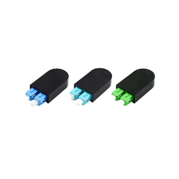
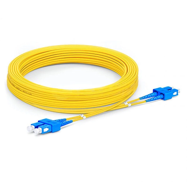
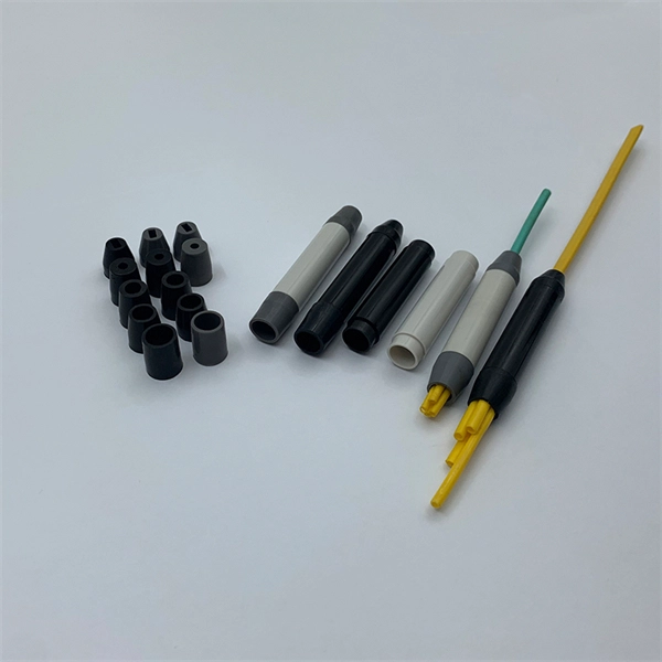
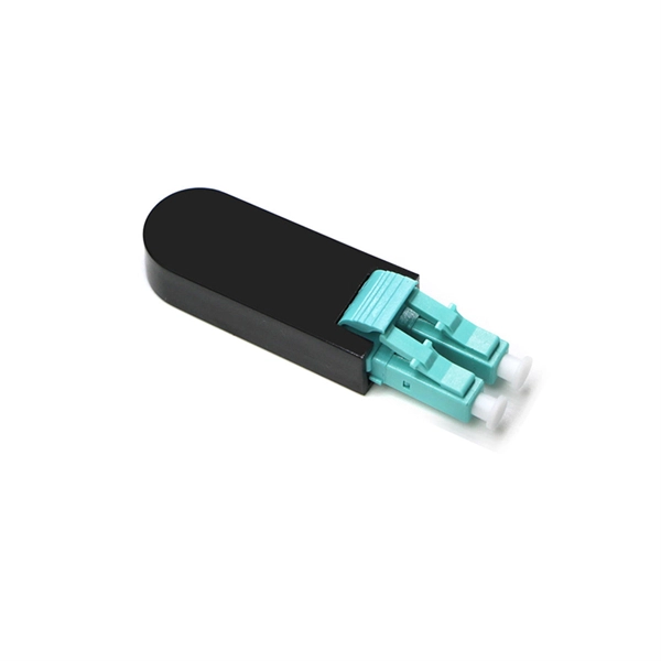
Get the wrong connector type, the wrong polish, or skip proper fusion splicing technique—and you're looking at elevated signal loss, increased back reflection, and a field termination that fails certification. Once you nail the logic chain— raw fiber → protected cable → spliced pigtail interfaces → flexible patching —you control loss budgets, installation time, and maintenance risk. Key takeaway: Treat the four items like a relay team. Each runs a specific leg so your network hits performance targets. In the intricate ecosystem of fiber optic networks, two components play a critical role in ensuring seamless connectivity: patch cords and pigtails. While both are essential for linking fibers to devices or other cables, they serve distinct purposes and are designed for specific scenarios. Executive Summary: A fiber optic pigtail is one of the most commonly specified yet least understood components in structured cabling. Despite their widespread use and numerous advantages, there are some circumstances in which they might not be the ideal option. A fiber optic pigtail is very practical for on-site terminations where fusion or mechanical splicers are used. Preterminated connectors offer several advantages over. Today, I'll show you how to pick the right patch cord or pigtail — step by step. A Fiber Patch cord connects two devices. You plug it into a switch, router, or patch panel. It's ready to use out of the box. A pigtail is for splicing.
[PDF]
CRU provides comprehensive, accurate and up-to-date price assessments and research reports for bare optical fibre across various key regional markets, combined with insights into the factors and events affecting markets. Market Forecast By Mode (Single Mode Fiber, Multi-Mode Fiber), By End-Use (Telecommunications, Networking, IT & Data Centers, Broadcast), By Application (Telecommunication, Power Utilities, Medical, Industrial), By Fiber Type (Glass Fiber, Plastic Fiber) And Competitive Landscape How does. Based on our observations and market communication with upstream suppliers, the single-mode fiber market in China has experienced an unprecedented price surge in the first two months of 2026. This article summarizes the latest fiber optic price data as of March 9, 2026, along with the recent. According to APO Research, The global Fiber Optic Cables market was valued at US$ million in 2023 and is anticipated to reach US$ million by 2030, witnessing a CAGR of xx% during the forecast period 2024-2030. North American market for Fiber Optic Cables is estimated to increase from $ million in. How does 6W market outlook report help businesses in making decisions? 6W monitors the market across 60+ countries Globally, publishing an annual market outlook report that analyses trends, key drivers, Size, Volume, Revenue, opportunities, and market segments.
[PDF]
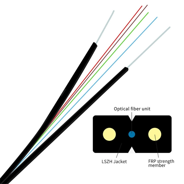
In this guide, we list the Top 5 Global Manufacturers who set the standard for fire safety. We will also clarify the confusing jargon (OFNR vs. IEC 60331) and show you how to source safety-compliant cables without breaking your budget. Discover premium quality flame retardant fiber optic cable designed to enhance connectivity and performance. Ideal for business buyers seeking reliable solutions. From enabling the energy transition with our pioneering E-Path sustainable cable solution, to supporting critical telecom infrastructure, Prysmian plays a pivotal role in building resilient and efficient systems across the globe. Our commitment to work closely with our customers ensures that we. These indoor fiber optic cables are used exclusively within buildings and must have a flame-retardant cable jacket to fit this purpose. Flame resistant cable may be deployed in-duct (conduit) or cable tray. These essential components are designed to transmit data efficiently, offering reliability and speed in communication systems. The many types of communication cables each have a specific composition, design, and function.
[PDF]
This Technical Brochure describes the induction phenomena (inductive, capacitive and conductive) that can lead to presence of voltage and currents on disconnected cable systems. The optical fiber composite overhead ground wire (OPGW) has been widely used in power transmission lines. Methods of calculation to evaluate those values and touch voltages are detailed and analysed, associated with various. working on cables u al, photocopying, recording or otherwise, without the prior written or use by members of the Energy Networks Association to take account of the conditions which apply to them. Advice should. Literature review: An in-depth literature review covering the modelling and calculations of the conditions relating to faults caused by interactions between fibre optic cables and power cores in submarine cables. Examples of electrically conductive installations where induced voltage may occur could be: • Overhead lines or cables out of opera- tion •.
[PDF]
The vertical clearance for overhead fiber optic lines above the highway must be a minimum of 18 feet. The exception is ADSS cables which are approved for installation in the power space by qualified personnel. All aerial cables should be installed clear of any obstructions. The Fiber Optic Association, Inc. (FOA) was founded in 1995 to help develop the workforce to build the fiber optic networks to support a rapid expansion in communications and the Internet. The charter of the FOA was to promote professionalism in fiber optics through education, certification, and. The basic pole height is 7m and the tip diameter is 150mm. In case of special sections, crossing obstacles or roads or railways, the pole height of 8m, 9m, etc. can be selected according to the actual terrain. If the surface is stone, the depth needs to be 0. 9m, and if the surface is other soil. Generally a 12 inch to 24 inch soil separation is recommended as a safety barrier and for locating purposes. 9938 | SuperiorEssexCommunications. com Page 1 of 4 TECHNICAL GUIDELINE July 30, 2020 TG030 Rev. FIBER is used for relocating any fiber optic cable from one location to another. Field conditions will vary, so the actual location. to n utral comm.
[PDF]
List of Top Verified Cabling and Fibre Optics Companies in Jordan, Near Me. Last updated May 2026. TechLine, a large-scale factory founded in Jordan in 2016, is situated in the Al Qastal industrial area of Amman. It holds ISO 9001:2008 certification, marking a milestone as the inaugural establishment of its kind in the Middle East. As part of a private investment consortium alongside Amwaj. Complete FTTx passive equipment - from fiber cables to distribution systems - plus reliable energy infrastructure, engineered with precision and trusted quality. Techline offers a. IT infrastructure and security solutions with quality commitment. Leading IT solutions in software, hardware, and networking. Complete networking solutions and services. Telephone: (5606205/3) Main Objectives: Manufacturing electric, power cables, and telephone wires. Let Optical Fiber Cables sellers contact you. No Time to Search? Post Your Buy Requirement to Suppliers Worldwide. Best prices, bulk discounts, trusted deals at go4WorldBusiness. Under the valuable guidance of Ziad Al-Omoush International Company for wires and cables manufacturing is now one of a fast growing company in the Hashemite Kingdom of Jordan with brand image of JOCAB. JOCAB manufactures a wide range of quality cables of high performance conforming to INTERNATIONAL.
[PDF]
The Iraqi Ministry of Communications is intensifying efforts to modernize the country's digital infrastructure through two major initiatives: the expansion of the national fiber-optic network and the launch of a new international submarine cable link. Together, these initiatives—domestic fiber expansion and international submarine connectivity—reflect the ministry's commitment to advancing Iraq's digital transformation, strengthening infrastructure, and integrating the country more deeply into global communications networks. The Iraqi Ministry. Baghdad (IraqiNews. com) – Iraq has solidified its position as a crucial transit gateway for international data traffic between Asia and Europe, following a strategic agreement between Ooredoo Group and the Iraqi Telecommunications and Post Company (ITPC). On August 27, Minister of Communications Dr. Hayam Al-Yasiri emphasized the strategic importance of the 24-pair fiber-optic cable, which has a. The Silk Route Transit Network is a fiber-optic infrastructure project developed by iQ Networks, a subsidiary of iQ Group Holding. Its purpose is to connect Europe and Asia through Iraq, avoiding traditional routes like the Red Sea and the Suez Canal. The project aims to serve as a key IP.
[PDF]
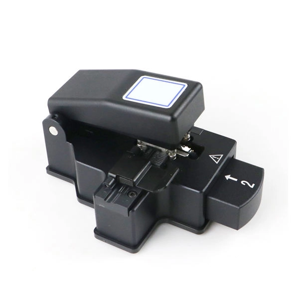
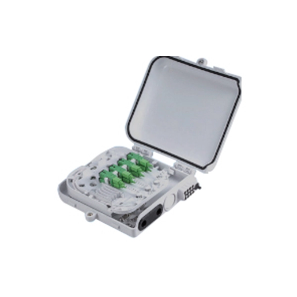
Proper fiber optic termination is a crucial process for ensuring the reliability, performance, and long-term durability of any fiber optic network. The process of fiber optic cable termination is the essential act of connecting fiber optic cables to devices, patch panels, or other. Fiber optic joints or terminations - where cables are terminated - are made two ways: 1) connectors that mate two fibers to create a temporary joint and/or connect the fiber to a piece of network gear (left) or 2) splices which create a permanent joint between the two fibers (right). Thus, you will put the cable across the points, stretch it to determine length, cut it accordingly, and place the connector on each end. After that, the patch panel attaches to it. Each cable has a connector attached. A. Once fiber optic cables have been successfully placed, we can focus on managing the ends of the fibers. This process depends on the project's needs and identifying a solution that aligns with the current situation. We can make suggestions that typically benefit the current circumstances and result. Where copper twisted pairs tend to terminate with an RJ45 plug, fiber optic connectors come in all sorts of shapes and sizes, with all manner of different use cases in mind. An optical fiber connector is used to join optical fibers where a connect/disconnect capability is required.
[PDF]
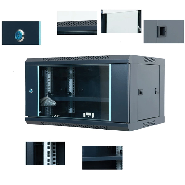
The modern world relies heavily on electrical and communication cables that must be managed and supported across vast distances in commercial and industrial settings. A cable tray is an organized support structure designed to secure and route these insulated electrical cables. In the electrical wiring of buildings, a cable tray system is used to support insulated electrical cables used for power distribution, control, and communication. Cable trays are used as an alternative to open wiring or electrical conduit systems, and are commonly used for cable management in. Whether you're planning a new office setup or upgrading your existing network, the choice of a cable tray system plays a significant role in ensuring the reliability and scalability of your structured cabling solution. It acts as a. en completely installed, without damage either to conductors or structural system use maintain spacing or to keep cables in place when the tray is ect the minimum bend ra-dius for cables as they exit the bottom of the cable tray. A rung spacing of 6 to 9 inches (150 to 230 mm) is preferable when. Explore various cable tray types and sizes for electrical installations. Learn about ladder, perforated, solid-bottom, wire mesh, and channel trays in this complete guide. What is Cable Tray Systems? 1.
[PDF]
View or download our complete Fiber Optic Cable Catalogue with detailed specifications, certifications, and technical information. RHINO Cable is one of the leading Power and Communication cables suppliers in Ethiopia with more than 10 years of experience. Explore our comprehensive range of high-quality electrical, telecom, and fiber optic cables. Our product catalogue features detailed specifications and images to help you find the right solution for your project needs. BMET Energy Telecom Industry and Trade PLC” is the biggest capacity electrical. The Ethiopia Fiber Optic Cable Market is poised for steady growth rate improvements from 2025 to 2029. 41% in 2025, the growth rate steadily ascends to 16. Manufacturing excellence with 700,000,000. General Symmetric cable pairs Land coaxial cable pairs Submarine cables Free space optical systems G. 649 Optical fibre cables G. 659 Characteristics of optical components and subsystems Characteristics of optical systems G. 679. In Ethiopia, Huawei unveiled its brand-new OptiXtremeTM 400G DR4 series of fibre optic cables. The cables come in a range of lengths and configurations, and they can transport data at rates of up to 400 Gbps. In. Tailor every aspect of your fiber optic solutions — from cable type, connector style, and jacket material to branding, labeling, and packaging. We're here to support your fiber network needs.
[PDF]
This document discusses techniques for trenching and laying optical fiber ducts. Installing fiber optic cables underground involves far more than digging trenches and placing cables. It forms a critical backbone for modern communication networks across both urban and rural environments. Project success depends on careful planning, precise installation practices, and proper. Installing underground fiber optic cables is critical to establishing high speed internet infrastructure that delivers reliable connectivity for businesses nationwide. Fiber optic cables are the shining stars of modern connectivity, transmitting data at lightning-fast speeds through glass. This comprehensive guide walks through the essential steps and best practices for successful underground fiber optic cable deployment, ensuring optimal performance and longevity of your network installation. Why Choose Underground Fiber Optic Installation? Underground fiber optic installations. Placing cables underground has the added benefits of reducing transmission losses, aiding planning consent and reduced risk of service supply loss through extreme weather.
[PDF]
Need some clarification about NEC 770. 47 (B), it says that the direct buried conductive fiber optic cable shall be 12 in (300 mm) away from the power cables. Separating high-voltage power cables from low-voltage communication cables is a fundamental requirement in any electrical installation. This practice is mandatory for two distinct reasons: ensuring the safety of the structure and its occupants, and preserving the integrity of sensitive data. Maintaining proper separation between power, data, and limited energy cabling is foundational to system performance, safety, and code compliance. Separation isn't just an EMI precaution — it protects signaling, reduces rework, and ensures pathways meet inspection expectations across risers. TECHNICAL GUIDELINE July 30, 2020 TG030 Rev. 4 Pathway Separation Between Telecommunication Cables and Power Cables Communications cables are, by design or necessity, often installed in close proximity and/or in the same pathway as power service cables. The electrical energy of the power cables can. This standard titled “Commercial Building Standard for Telecommunications Pathways and Spaces” is a joint publication of ANSI/TIA/EIA. Its current version (ANSI/TIA/EIA/-569-B) was published in October 1, 2004 and describes EMI aspects in Article 10. ca with numerous contributions by others. "UTP Separation Guidelines From EMI Sources". The values are the same as the cabling pathways standard, EIA-569, table 4.
[PDF]