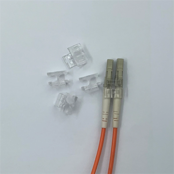
Fiber optic cables can be run anywhere from 2 kilometers to over 100 kilometers without signal regeneration, depending on the cable type and application. Fiber optic cable transmission distance is determined by two primary physical factors that affect signal quality as light travels through the fiber medium. The greater the distance, the greater. In this blog, I will discuss the fiber optic cable distance, the effect factors, how to choose the right fiber optic cables, and how to compare the transmission distances of single-mode and multimode fiber optic cables. Single-mode fiber (SMF) supports distances up to 40-100+ kilometers for standard applications, while multimode fiber (MMF) is typically limited. Fiber optic cables are the backbone of modern communications, enabling high-speed data transfer over vast distances. Unlike traditional copper cables, fiber optic cables use light to transmit data, resulting in faster speeds and greater bandwidth capabilities. Chromatic dispersion This is a key factor affecting single mode fiber distance. While this technology offers higher speeds and longer distances than traditional copper wiring, physical limitations impose distance constraints. Light pulses degrade as they travel over long spans, primarily.
[PDF]
Calculate and select the right number and spacing of cables for junction boxes using NEC guidelines to ensure safe, code-compliant electrical installations. Electrical clearances set the minimum safe distances for panels, overhead lines, pools, and buried wiring — and ignoring them has real consequences. 7* Class A and Class X circuits using physical conductors (e., metallic, optical fiber) shall be installed such that the outgoing and return conductors, exiting from and returning to the control unit, respectively, are routed separately. The outgoing and return (redundant) circuit conductors. Above finished grade or sidewalks, or from any platform or projection from which they might be reached. (If these areas are accessible to other than pedestrian traffic, then one of the other conditions applies). This step keeps your project safe and. In this guide, we'll break down everything you need to know to install a distribution box correctly and confidently. Choose the right box based on environment (indoor/outdoor), load capacity, and durability. Check for proper IP/NEMA ratings and material quality. Ensure safe placement: install in. When looking into electrical panel clearance safety, you need to start by looking at the requirements put in place by the national electric code, or NEC. The relevant section of the national electric code here is NEC 110. This set of code identifies how much clearance is needed around any type.
[PDF]
Because the detecting distances range from a couple inches to several meters, adjustment during installation is incredibly easy. Detection is possible even for small targets. Retro-reflective models detect the amount of light returned from a reflector installed opposite of the. Fine spot lens NF-DA03 and coaxial diffuse Fiber-OpticCable NF-DK21 enables ø0. The NF-DA06 comes with a small spot lens where sensing distance and spot size can be adjusted through the amount of fiber inserted. It is possible to change the spot size between ø0. 9 mm with a. Optical fiber sensors (OFSs) have emerged as essential tools in the monitoring of physical, chemical, and bio-medical parameters in harsh situations due to their high sensitivity, electromagnetic interference (EMI) immunity, and long-term stability. However, the current literature contains. A fiber-optic sensor is a sensor that uses optical fiber either as the sensing element ("intrinsic sensors"), or as a means of relaying signals from a remote sensor to the electronics that process the signals ("extrinsic sensors"). Fibers have many uses in remote sensing. Depending on the. There are several types of fiber optic sensors. Detection methods include thrubeam, reflective, retro-reflective, and definite-reflective. Thrubeam models include a transmitter and receiver installed opposite each other.
[PDF]
The Optical Time Domain Reflectometer (OTDR) is useful for testing the integrity of fiber optic cables. It can verify splice loss, measure length and find faults. in cable TV, LAN, metropolitan networks or long-haul. Ensure the integrity of your fiber optic network with an Optical Time Domain Reflectometer (OTDR). OTDR testing analyzes fiber optic cable performance from end to end by testing components along the cable, including connection points, bends, and splices. It injects a series of optical pulses into the fiber and analyzes the backscattered signal based on time, enabling a detailed view of the. 15 EXFO Inc. No part of this publication may be reproduced, stored in a retrieval system or transmitted in any form, be it electronically, mechanically, or by any other means such as photocopying, recording or otherwise, without the prior writt eved to be accurate and reliable. From a single end of the link, it can determine the magnitude and location of loss, detect reflections, and visualize events along the fiber. An OTDR injects a series of optical.
[PDF]
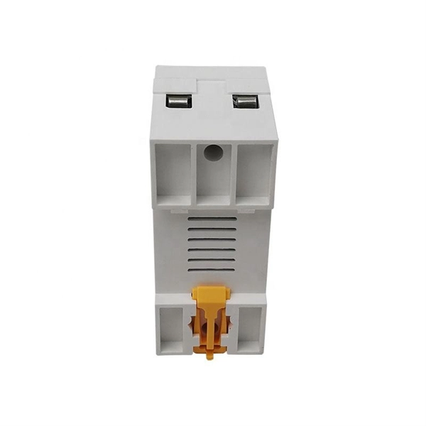
Distribution box and switch box should not exceed 30 meters. Learn how to install a distribution box safely and correctly. Covers wiring, placement, standards, and expert tips for a compliant setup. It takes the incoming power and safely distributes it to different circuits throughout your building. Generally, distribution boxes can be divided into three levels of secondary protection, that is, three levels of distribution boxes: general. Electrical clearances set the minimum safe distances for panels, overhead lines, pools, and buried wiring — and ignoring them has real consequences. Electrical clearances are the minimum separation distances the National Electrical Code (NEC) requires between wiring, panels, overhead conductors. I'm here to help you figure it out — no jargon, no hassle. COPYRIGHT © 2026 INTERNATIONAL CODE COUNCIL, INC. ICC Digital Codes is the largest provider of model codes, custom codes and standards used worldwide to. NEC 300. 5 is an article in the National Electrical Code that addresses requirements for underground electrical installations, including minimum cover requirements—the measurement used to determine the distance from the top of an underground cable or raceway to the finished grade.
[PDF]
Oxygen and acetylene cylinders must be stored at least 20 feet apart, or separated by a noncombustible barrier at least 5 feet tall with a minimum half-hour fire-resistance rating. Learn how OSHA requires you to store oxygen and acetylene cylinders safely, including separation distances, indoor limits, and handling empty tanks. 253 is the federal rule for oxygen-fuel gas welding and cutting in general industry. It sits in 29 CFR 1910 Subpart Q alongside three sister sections: 1910. 251 (definitions), 1910. 252 (general welding — fire prevention, PPE, ventilation, confined spaces), 1910. 254 (arc welding). Alternatively, there is no requirement for space between flammable and oxidizing gases if a minimum 5ft. This code review also outlines other important and relevant information. information, refer to the Compressed Gas Association (CGA) for Pamphlet P-1. Always separate gases by type and keep them in assigned, clearly identified locations. OSHA requires that cylinders containing flammable gases are either stored at least 20 feet (6. 1m) feet from highly combustible materials such as oil or excelsior. Cylinders should be stored in definitely assigned places away from elevators, stairs, or gangways. (b) The distribution piping must include a means, located as close to the supply cylinders as possible, of regulating the discharge pressure from the supply.
[PDF]
Generally, standard trays require supports every 6 to 10 feet, while heavy-duty, long-span trays can handle distances of up to 20 feet between supports. To determine the proper spacing, consult the manufacturer's load capacity chart, which accounts for the total weight of the. The following are a few points to consider when dealing with cable tray and the National Electrical Code. This is a description of how to select, install, and support these metal or plastic frames, on which electrical wires are installed. You should consider it as a series of instructions that make the buildings resistant to. Support spacing for cable trays must align with the manufacturer's instructions, as outlined in NEC 392. This spacing is crucial for adequate maintenance access, ease of inspection, and ensuring proper airflow for effective heat dissipation. It also helps reduce the risk of. In this installment of our Code Corner series, Ryan Mayfield focuses on the 2023 National Electrical Code (NEC) changes concerning cable trays, particularly section 690. Historically, the NEC has allowed cable trays, but has lacked specific guidelines for sizing conductors and using smaller. This guide covers the critical steps, from selecting the right electrical cable tray and performing accurate cable fill calculations to managing a safe cable pull through and ensuring all bonding and grounding requirements are met. For licensed electricians, mastering these principles is essential.
[PDF]