We offer EVA- and PE-based masterbatches for LSZH/HFFR compounds, as well as PBT-based masterbatches used in buffer tube applications for optical fibers. At Delta Tecnic, a global leader in cable masterbatch innovation, we specialize in developing advanced masterbatch solutions tailored to meet the stringent technical, safety, and aesthetic requirements of the wire and cable industry. This blog explores how Delta Tecnic's cable masterbatch solutions. Ampacet, a global masterbatch leader, has expanded its ELTech™ portfolio to include a range of high performance color masterbatches based on a Polybutylene Terephthalate (PBT) carrier resin and specifically designed for optical fiber cable PBT jacketing. Optical fiber cable jacketing is often made of PBT to benefit from its. At Polytec Masterbatch LLC, a leading manufacturer and supplier of Masterbatch in UAE and worldwide, we provide cutting-edge masterbatch solutions that drive innovation, enhance durability, and elevate design possibilities. Let's explore how masterbatch is shaping industries globally, thanks to its.
[PDF]
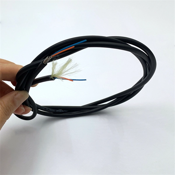
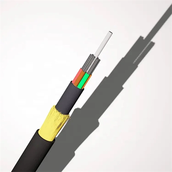
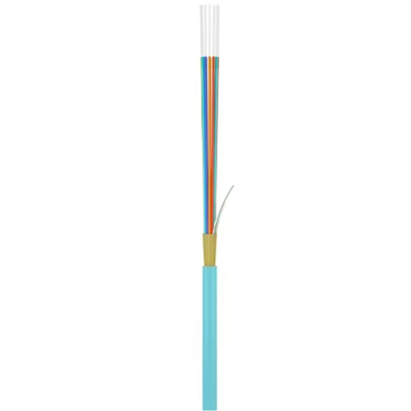
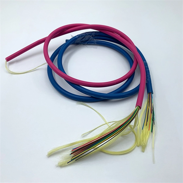
This guide breaks down the five core components of a fiber optic cable — from the specification package to the actual installation considerations. You will also learn how different aspects of the product can affect budget and design. ■ The Five Key Parts of a Fiber . Fiber optic cables are designed to provide high-speed, no-signal-loss, and EMI-free communication in telecommunication, powergrid, datacenter, broadband, and industrial applications. Each optical cable is constructed using a precise combination of optical fibers, strength members, buffer tubes. How does 6W market outlook report help businesses in making decisions? 6W monitors the market across 60+ countries Globally, publishing an annual market outlook report that analyses trends, key drivers, Size, Volume, Revenue, opportunities, and market segments. The material composition determines the fiber's performance, including how far and how fast data can travel. The choice of material is an engineering decision driven by the need to. But are you wondering what materials fiber optic cables are made of? The most common materials are glass and plastic. To transmit information, a datalink converts an analog electronic signal—a telephone conversation or the output of a video camera—into digital pulses of laser light.
[PDF]
CRU provides comprehensive, accurate and up-to-date price assessments and research reports for bare optical fibre across various key regional markets, combined with insights into the factors and events affecting markets. Market Forecast By Mode (Single Mode Fiber, Multi-Mode Fiber), By End-Use (Telecommunications, Networking, IT & Data Centers, Broadcast), By Application (Telecommunication, Power Utilities, Medical, Industrial), By Fiber Type (Glass Fiber, Plastic Fiber) And Competitive Landscape How does. Based on our observations and market communication with upstream suppliers, the single-mode fiber market in China has experienced an unprecedented price surge in the first two months of 2026. This article summarizes the latest fiber optic price data as of March 9, 2026, along with the recent. According to APO Research, The global Fiber Optic Cables market was valued at US$ million in 2023 and is anticipated to reach US$ million by 2030, witnessing a CAGR of xx% during the forecast period 2024-2030. North American market for Fiber Optic Cables is estimated to increase from $ million in. How does 6W market outlook report help businesses in making decisions? 6W monitors the market across 60+ countries Globally, publishing an annual market outlook report that analyses trends, key drivers, Size, Volume, Revenue, opportunities, and market segments.
[PDF]
Abstract: Detecting partial discharges in cable joints is critical for timely defect identification and reliable transmission system operation. The electric field distribution of the optical fiber-implanted cable joint was simulated, followed by electrical performance tests, demonstrating that optical fiber implantation had a negligible effect on the electrical properties of the cable joint. A platform utilizing Mach–Zehnder–Sagnac. The results show that the average sensitivity of the sensor in the 10 kHz–80 kHz range is 71. 0 dB higher than that of the piezoelectric transducer, with a maximum signal-to-noise ratio of 65. To improve the long-term reliability and sensitivity of the sensing system, a novel method for cable joint monitoring based on implanting optical fibers. However, there is an industry gap in the literature about the highly sensitive fiber optic-based PD solution based on the acoustic emission principle. This paper aims to fill such an industry gap. In this paper, the fiber optic-based PD sensing (OptiFender) technology is applied to monitor the PD.
[PDF]

Discover the key differences between optical fiber cables and copper cables. OPTRAL analyzes the advantages and disadvantages to enhance connectivity. Optical and copper interconnection technologies represent two distinct approaches to data transmission, each with its own advantages and limitations. While fiber optics dominate in performance, copper retains its technical and economic justification. But how do you decide which one is best suited for your needs? This article delves into the technical comparison between copper and fiber optic cables. When it comes to modern data transmission, Fiber Optic cables and Copper Cables play pivotal roles in ensuring seamless connectivity. What Are Fiber Optic Cables? Fiber Optic cables function by transmitting data in the form of light pulses through optically pure glass fibers. These fibers are. “Fiber offers multiple technical advantages, including exceptional bandwidth, low attenuation and distortion over long distances, reduced bulk, as well as isolation from electromagnetic interference (EMI) and electrostatic discharge (ESD). ” Let's explore the characteristics, advantages, and. The two core material technologies used in almost all cables are fiber optic, and copper wiring. Whether you're looking at an HDMI cable, a USB cable, Ethernet patch cable, or any other kind of network of data transmission cabling, they are all built using copper or fiber optic internal wiring.
[PDF]
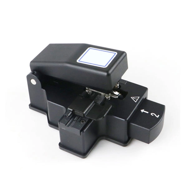
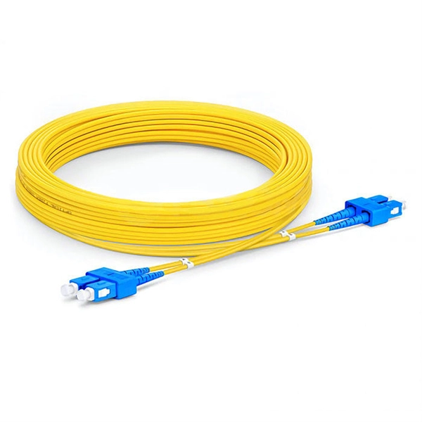
Get the wrong connector type, the wrong polish, or skip proper fusion splicing technique—and you're looking at elevated signal loss, increased back reflection, and a field termination that fails certification. Once you nail the logic chain— raw fiber → protected cable → spliced pigtail interfaces → flexible patching —you control loss budgets, installation time, and maintenance risk. Key takeaway: Treat the four items like a relay team. Each runs a specific leg so your network hits performance targets. In the intricate ecosystem of fiber optic networks, two components play a critical role in ensuring seamless connectivity: patch cords and pigtails. While both are essential for linking fibers to devices or other cables, they serve distinct purposes and are designed for specific scenarios. Executive Summary: A fiber optic pigtail is one of the most commonly specified yet least understood components in structured cabling. Despite their widespread use and numerous advantages, there are some circumstances in which they might not be the ideal option. A fiber optic pigtail is very practical for on-site terminations where fusion or mechanical splicers are used. Preterminated connectors offer several advantages over. Today, I'll show you how to pick the right patch cord or pigtail — step by step. A Fiber Patch cord connects two devices. You plug it into a switch, router, or patch panel. It's ready to use out of the box. A pigtail is for splicing.
[PDF]
While fiber itself is constructed of thin, fragile filaments of glass, fiber cables that are laid outdoors are built for durability. Fiber optic internet represents a significant leap forward in broadband technology, offering speeds and reliability far exceeding traditional cable or DSL connections. Unlike older technologies that rely on electrical signals transmitted through copper wires, fiber optics use thin strands of glass. Unlike traditional copper wires that carry electrical signals, fiber optics use thin strands of glass or plastic to transmit data as pulses of light. This fundamental difference is the key to its superior speed, bandwidth, and reliability. The light signals travel at near the speed of light. Installing fiber optic cables underground involves far more than digging trenches and placing cables. It forms a critical backbone for modern communication networks across both urban and rural environments. Unlike traditional copper systems, fiber optic cables require specialized handling techniques and precise installation methods to. In our digital age, high-speed internet and reliable communication networks are powered by fiber optic cables, which transmit data as light signals at incredible speeds. However, the performance of fiber optic technology depends heavily on proper fiber optic cable installation.
[PDF]
Fiber optic splitters offer a cost-effective, practical solution by dividing a single fiber line into multiple outputs. This guide delivers hands-on advice to help readers implement network expansion affordably and efficiently, transforming limited resources into scalable. Before diving into the possibility of splitting an optical cable, it's essential to understand the basics of how they work. Optical cables, also known as fiber optic cables, consist of thin strands of glass or plastic fibers surrounded by a protective casing. These fibers transmit data as light. These unassuming devices enable a single optical signal to be divided into multiple paths, making them indispensable for sharing network resources efficiently—from residential FTTH (Fiber-to-the-Home) connections to large-scale telecom backbones. It can divide the input optical signal into multiple output optical signals to meet the fiber optic access needs of multiple terminal devices. This type of device plays an important role in passive. This device plays a pivotal role in Passive Optical Networks (PONs), enabling the distribution of optical signals across multiple end-users while maintaining signal integrity. Fiber optic splitters have applications such as Fiber to the Home (FTTH) and Passive Optical Networks (PONs).
[PDF]
Fiber optic cables are also more secure, as they are harder to tap or hack. Fiber and copper cable repair both require trained splicers, but the tools, techniques, and failure modes are completely different. Sending a fiber splicer to repair a copper cable - or vice versa - wastes time and risks making the damage worse. Here is what you need to know before you call for. Well-made fiber optic cables are very tough, making them great choices for homeowners who would like to limit weather-related internet outages as much as possible. The comparatively high durability of fiber optic cables comes from a series of factors, including: The quality of the glass cables, of. Copper and fiber optic cables each offer distinct advantages and disadvantages that can impact performance, cost, and long-term efficiency. But how do you decide which one is best suited for your needs? This article delves into the technical comparison between copper and fiber optic cables. Fiber optic cables are typically damaged in one of two ways: A premade fiber optic cable suffers connector damage when too much pull-force is applied during installation. This can occur on long cable runs through tight conduit or duct, and also if the cable becomes caught or snagged.
[PDF]
Q: How far can multimode fiber go? A: The transmission distance of multimode fiber depends on the fiber type and data rate. OM3 and OM4 multimode fibers typically support up to 300m and 400m, respectively, for 10G Ethernet. At lower data rates, such as 1G Ethernet, multimode fiber. Multimode fiber optic cables are designed to carry multiple light modes simultaneously, each taking a different path or mode through the fiber. This characteristic makes MMF ideal for high-bandwidth applications over relatively short distances. Common applications include Local Area Networks. Fiber optic cable transmission distance is determined by two primary physical factors that affect signal quality as light travels through the fiber medium. The greater the distance, the greater. A: Single mode fiber can typically transmit up to 160 km, and with dispersion compensation, it can exceed 200 km. For most enterprise or data center applications using multimode fiber, the practical limit sits between 300 m and 550 m. However, the dispersion-compensating fibers can support more than 200 kilometers. How. For instance, without amplifiers, single-mode fiber can reach 50-60 miles and can support data rates of 1 Gbps or 10 Gbps. With amplifiers, such as Erbium-doped fiber amplifiers (EDFAs), the distance can be extended to 600 miles or more, and even further with additional amplifiers for long-haul.
[PDF]
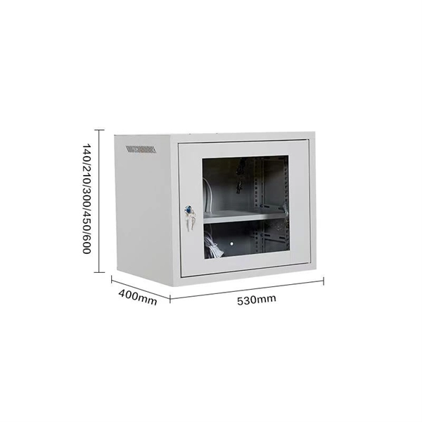
The modern world relies heavily on electrical and communication cables that must be managed and supported across vast distances in commercial and industrial settings. A cable tray is an organized support structure designed to secure and route these insulated electrical cables. In the electrical wiring of buildings, a cable tray system is used to support insulated electrical cables used for power distribution, control, and communication. Cable trays are used as an alternative to open wiring or electrical conduit systems, and are commonly used for cable management in. Whether you're planning a new office setup or upgrading your existing network, the choice of a cable tray system plays a significant role in ensuring the reliability and scalability of your structured cabling solution. It acts as a. en completely installed, without damage either to conductors or structural system use maintain spacing or to keep cables in place when the tray is ect the minimum bend ra-dius for cables as they exit the bottom of the cable tray. A rung spacing of 6 to 9 inches (150 to 230 mm) is preferable when. Explore various cable tray types and sizes for electrical installations. Learn about ladder, perforated, solid-bottom, wire mesh, and channel trays in this complete guide. What is Cable Tray Systems? 1.
[PDF]
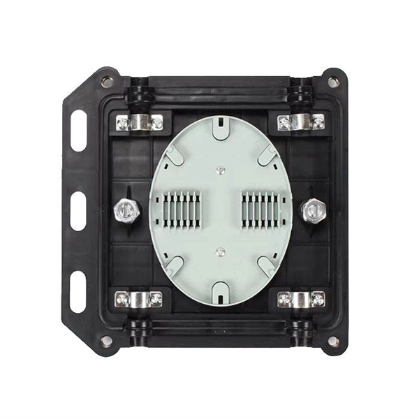
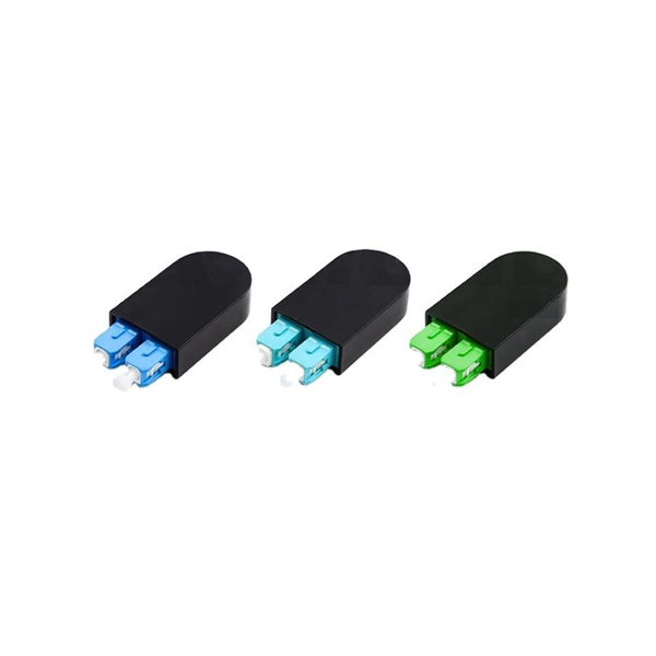
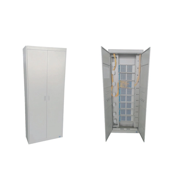
Proper fiber optic termination is a crucial process for ensuring the reliability, performance, and long-term durability of any fiber optic network. The process of fiber optic cable termination is the essential act of connecting fiber optic cables to devices, patch panels, or other. Fiber optic joints or terminations - where cables are terminated - are made two ways: 1) connectors that mate two fibers to create a temporary joint and/or connect the fiber to a piece of network gear (left) or 2) splices which create a permanent joint between the two fibers (right). Thus, you will put the cable across the points, stretch it to determine length, cut it accordingly, and place the connector on each end. After that, the patch panel attaches to it. Each cable has a connector attached. A. Once fiber optic cables have been successfully placed, we can focus on managing the ends of the fibers. This process depends on the project's needs and identifying a solution that aligns with the current situation. We can make suggestions that typically benefit the current circumstances and result. Where copper twisted pairs tend to terminate with an RJ45 plug, fiber optic connectors come in all sorts of shapes and sizes, with all manner of different use cases in mind. An optical fiber connector is used to join optical fibers where a connect/disconnect capability is required.
[PDF]
Drawing on IEC standards and industry research data, it outlines the coverage of mainstream outdoor fiber optic cable types, selection criteria, and best practices for installation, providing a systematic reference for outdoor fiber optic cable deployment. This document serves as a guide for outdoor fiber optic cable selection and installation for professionals in the telecommunications industry. Fiber optic cables for outdoor applications are engineered to withstand the more demanding conditions seen outside, from environmental extremes to mechanical forces. These are the outdoor fiber optic cables you see strung along telephone poles (aerial), installed inside an underground duct, or even. Outdoor fiber optic cables transport data and communications signals over long distances while enduring extreme environments. Whether you're linking buildings, running broadband in rural areas, or building 5G infrastructure, the right cable matters. It affects performance, maintenance, cost, and reliability. Our team will make sure the configuration is tailored to your needs and will provide a detailed quote. Email us using the Request a Quote below, or. hing, conduit and temp rature variations. The Outside Plant cable. These cables are thoroughly tested designed for installation in pathways that are subjected to wide product line offers 6 and 12 fibers per and verified to Telcordia GR 20 a loose tube cables and hybrid design o ts to specific.
[PDF]
Naficon Liitin Oy, the parent company based out of Finland is one of the most trusted suppliers for telecom, data centers and utility across Northern Europe. Naficon Fiber Optic Manufacturing LLC in Dubai, UAE serves as a major Manufacturing and Supply Centre in the Middle East. We are a leading manufacturer of Optic Fiber Cables in the United Arab Emirates. With advanced technology, strict quality standards. The United Arab Emirates (UAE) is a thriving hub for fiber optic cable manufacturing, offering advanced solutions to meet the region's growing demand for high-speed internet and reliable telecommunications infrastructure. Here, we explore some of the leading fiber optic cable manufacturers in the. The best connection for your application. New web catalogue, with productfinder and new search function. Search the complete range of products of Lapp Group. This website uses cookies and similar technologies (hereinafter "cookies"). Providing a happier, richer future through providing solutions for copper and optical communication for the past 20 Years. Established to meet the evolving needs of the telecommunication infrastructure network, AFOC focuses on delivering innovative, customized, and competitive optic fiber cable products. NAFICON is a fiber industry expert with over 30 years of manufacturing legacy.
[PDF]
Use this worksheet to input values for all variables that will impact your system's performance. After entering your values, please ensure you click the 'Calculate Link Loss' button at the bottom of the page to generate your total link loss. Add connectors, splices, bends, and safety margin easily. See results instantly above the form, then adjust values. Choose a mode, then enter values and optional losses. All calculations use base-10 logarithms. mW must be greater than zero. Used only in measured attenuation mode. Length is needed. The power budget refers to the amount of fiber optic cable plant loss that a datalink (transmitter to receiver) can tolerate in order to operate properly. Sometimes the power budget has both a minimum and maximum value, which means it needs at least a minimum value of loss so that it does not. To detect whether the link runs properly, the following calculation should be performed. It is often the case to calculate the maximum signal loss across a given fiber link during optical cable installation. First, you should be aware of the fiber loss formula: The Total Link Loss = Cable. Therefore, it is very important to calculate the fiber loss and take appropriate steps. In order to get the most reliable results, an Optical Time Domain Reflectometer (OTDR) trace of the actual fiber connection should be completed. This will provide you with the real.
[PDF]