The price per foot includes the fiber itself, connectors, and basic installation factors, with main drivers being cable type, distance, and any required conduit or termination hardware. This article outlines cost expectations, price ranges, and practical savings. Fiber-optic cable materials typically cost $1 to $6 per linear foot, depending on fiber count and cable type. Commercial building installations with 100-200 network drops generally range from $15,000 to $30,000. Single-mode fiber costs less per foot than multimode fiber, but it requires more. Typically, per drop fiber cabling prices range from $250 – $1000 per drop depending on the type of fiber (OM2, OM3, OM4, or OM5), multi or single mode, PVC or plenum, average drop length, and also the number of fibers in each cable. This. Whether you need singlemode, armored, or indoor plenum, this guide gives you the exact cost per foot of fiber optic cable — including installation — so you can budget without guesswork. Data aggregated from Q1 2026 contractor invoices across Texas, Ohio, and North Carolina. The installation type you choose and the layout of your property determine the total labor and materials needed for your project. Cost for fiber cabling projects.
[PDF]
CRU provides comprehensive, accurate and up-to-date price assessments and research reports for bare optical fibre across various key regional markets, combined with insights into the factors and events affecting markets. Market Forecast By Mode (Single Mode Fiber, Multi-Mode Fiber), By End-Use (Telecommunications, Networking, IT & Data Centers, Broadcast), By Application (Telecommunication, Power Utilities, Medical, Industrial), By Fiber Type (Glass Fiber, Plastic Fiber) And Competitive Landscape How does. Based on our observations and market communication with upstream suppliers, the single-mode fiber market in China has experienced an unprecedented price surge in the first two months of 2026. This article summarizes the latest fiber optic price data as of March 9, 2026, along with the recent. According to APO Research, The global Fiber Optic Cables market was valued at US$ million in 2023 and is anticipated to reach US$ million by 2030, witnessing a CAGR of xx% during the forecast period 2024-2030. North American market for Fiber Optic Cables is estimated to increase from $ million in. How does 6W market outlook report help businesses in making decisions? 6W monitors the market across 60+ countries Globally, publishing an annual market outlook report that analyses trends, key drivers, Size, Volume, Revenue, opportunities, and market segments.
[PDF]
This section explains aspects of digital input and output, from applications and types to interface circuit characteristics, in an easy-to-understand way. What is a digital I/O board? 2. Bidirectional I/O circuit 6. The Ace PLC can interface any DC voltage signal between 3 and 30 VDC. Typical system designs utilize 5 V, 12 V or 24 VDC. Any connection to DC voltage between 1. 5 and 30 VDC is sensed as a '1'. The ground. WARNING: Identifies information about practices or circumstances that can cause an explosion in a hazardous environment, which may lead to personal injury or death, property damage, or economic loss. In this article, we are sharing the basic concepts of PLC and DCS control systems Wiring Diagrams for Digital Input (DI), Digital Output (DO), Analog Input. In the introduction section, you'll find a history of Arrow Hart products dating back 130 years, instructions on how to use the buyer's guide, a detailed NEMA configuration chart for straight blade & locking devices and a pin & sleeve and mechanical interlock configuration chart. Eaton's extensive. Digital inputs are activated by making a connection from the input channel to system ground (0V DC): In practice, several inputs are integrated into one module. The 24V DC supply is used for the internal electronics, and may also be used to power input devices. An active signal from an Input device.
[PDF]
Abstract: Detecting partial discharges in cable joints is critical for timely defect identification and reliable transmission system operation. The electric field distribution of the optical fiber-implanted cable joint was simulated, followed by electrical performance tests, demonstrating that optical fiber implantation had a negligible effect on the electrical properties of the cable joint. A platform utilizing Mach–Zehnder–Sagnac. The results show that the average sensitivity of the sensor in the 10 kHz–80 kHz range is 71. 0 dB higher than that of the piezoelectric transducer, with a maximum signal-to-noise ratio of 65. To improve the long-term reliability and sensitivity of the sensing system, a novel method for cable joint monitoring based on implanting optical fibers. However, there is an industry gap in the literature about the highly sensitive fiber optic-based PD solution based on the acoustic emission principle. This paper aims to fill such an industry gap. In this paper, the fiber optic-based PD sensing (OptiFender) technology is applied to monitor the PD.
[PDF]
Fiber optic cables can be run anywhere from 2 kilometers to over 100 kilometers without signal regeneration, depending on the cable type and application. Fiber optic cable transmission distance is determined by two primary physical factors that affect signal quality as light travels through the fiber medium. The greater the distance, the greater. In this blog, I will discuss the fiber optic cable distance, the effect factors, how to choose the right fiber optic cables, and how to compare the transmission distances of single-mode and multimode fiber optic cables. Single-mode fiber (SMF) supports distances up to 40-100+ kilometers for standard applications, while multimode fiber (MMF) is typically limited. Fiber optic cables are the backbone of modern communications, enabling high-speed data transfer over vast distances. Unlike traditional copper cables, fiber optic cables use light to transmit data, resulting in faster speeds and greater bandwidth capabilities. Chromatic dispersion This is a key factor affecting single mode fiber distance. While this technology offers higher speeds and longer distances than traditional copper wiring, physical limitations impose distance constraints. Light pulses degrade as they travel over long spans, primarily.
[PDF]

Discover the key differences between optical fiber cables and copper cables. OPTRAL analyzes the advantages and disadvantages to enhance connectivity. Optical and copper interconnection technologies represent two distinct approaches to data transmission, each with its own advantages and limitations. While fiber optics dominate in performance, copper retains its technical and economic justification. But how do you decide which one is best suited for your needs? This article delves into the technical comparison between copper and fiber optic cables. When it comes to modern data transmission, Fiber Optic cables and Copper Cables play pivotal roles in ensuring seamless connectivity. What Are Fiber Optic Cables? Fiber Optic cables function by transmitting data in the form of light pulses through optically pure glass fibers. These fibers are. “Fiber offers multiple technical advantages, including exceptional bandwidth, low attenuation and distortion over long distances, reduced bulk, as well as isolation from electromagnetic interference (EMI) and electrostatic discharge (ESD). ” Let's explore the characteristics, advantages, and. The two core material technologies used in almost all cables are fiber optic, and copper wiring. Whether you're looking at an HDMI cable, a USB cable, Ethernet patch cable, or any other kind of network of data transmission cabling, they are all built using copper or fiber optic internal wiring.
[PDF]
The vertical clearance for overhead fiber optic lines above the highway must be a minimum of 18 feet. The exception is ADSS cables which are approved for installation in the power space by qualified personnel. All aerial cables should be installed clear of any obstructions. The Fiber Optic Association, Inc. (FOA) was founded in 1995 to help develop the workforce to build the fiber optic networks to support a rapid expansion in communications and the Internet. The charter of the FOA was to promote professionalism in fiber optics through education, certification, and. The basic pole height is 7m and the tip diameter is 150mm. In case of special sections, crossing obstacles or roads or railways, the pole height of 8m, 9m, etc. can be selected according to the actual terrain. If the surface is stone, the depth needs to be 0. 9m, and if the surface is other soil. Generally a 12 inch to 24 inch soil separation is recommended as a safety barrier and for locating purposes. 9938 | SuperiorEssexCommunications. com Page 1 of 4 TECHNICAL GUIDELINE July 30, 2020 TG030 Rev. FIBER is used for relocating any fiber optic cable from one location to another. Field conditions will vary, so the actual location. to n utral comm.
[PDF]
In this guide, we list the Top 5 Global Manufacturers who set the standard for fire safety. We will also clarify the confusing jargon (OFNR vs. IEC 60331) and show you how to source safety-compliant cables without breaking your budget. Discover premium quality flame retardant fiber optic cable designed to enhance connectivity and performance. Ideal for business buyers seeking reliable solutions. From enabling the energy transition with our pioneering E-Path sustainable cable solution, to supporting critical telecom infrastructure, Prysmian plays a pivotal role in building resilient and efficient systems across the globe. Our commitment to work closely with our customers ensures that we. These indoor fiber optic cables are used exclusively within buildings and must have a flame-retardant cable jacket to fit this purpose. Flame resistant cable may be deployed in-duct (conduit) or cable tray. These essential components are designed to transmit data efficiently, offering reliability and speed in communication systems. The many types of communication cables each have a specific composition, design, and function.
[PDF]
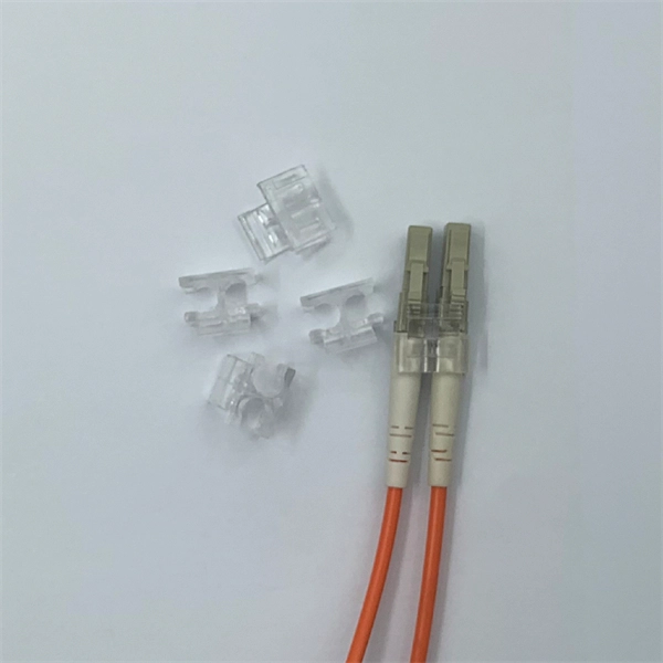
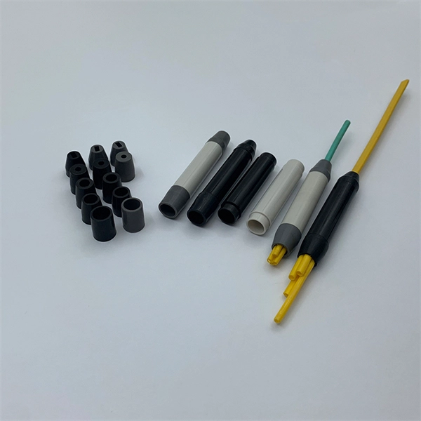
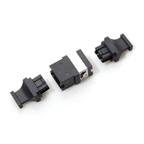
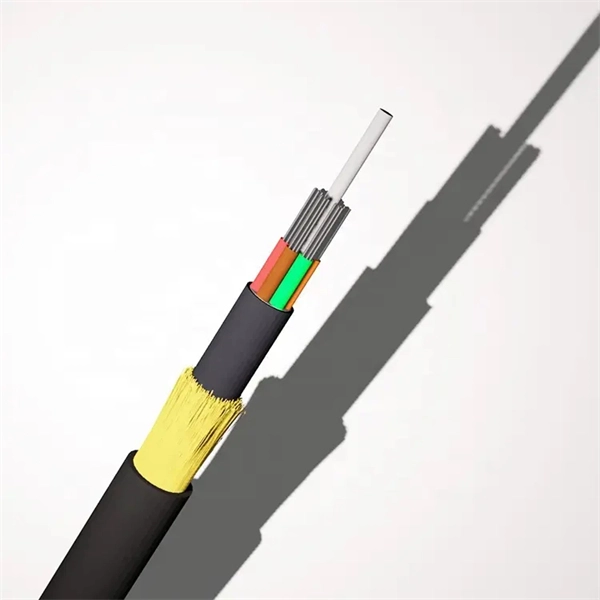
Fiber optic "cable" refers to the complete assembly of fibers, other internal parts like buffer tubes, ripcords, stiffeners, strength members all included inside an outer protective covering called the jacket. Cable provides protection for the optical fiber or fibers within it appropriate for the environment in which it is installed. You will also learn how different aspects of the product can affect budget and design. ■ The Five Key Parts of a Fiber Optic Cable A fiber optic cable. A fiber optic cable consists of five basic components: the core, the cladding, the coating, the strengthening fibers, and the cable jacket. When searching for a fiber optic cable, we need to pay attention not only to the connectors, such as SC to ST fiber cable, LC to SC fiber patch cable, or SC to. A TOSLINK optical fiber cable with a clear jacket. These cables are used mainly for digital audio connections between devices. This advanced cabling solution allows fast, secure data transfer and telecom over long distances. Understanding the components within a fiber optic cable enables. While fiber optic cable itself is cheaper than an equivalent length of copper cable, fiber optic cable connectors and the equipment needed to install them have typically been more expensive than their copper counterparts.
[PDF]
List of Top Verified Cabling and Fibre Optics Companies in Jordan, Near Me. Last updated May 2026. TechLine, a large-scale factory founded in Jordan in 2016, is situated in the Al Qastal industrial area of Amman. It holds ISO 9001:2008 certification, marking a milestone as the inaugural establishment of its kind in the Middle East. As part of a private investment consortium alongside Amwaj. Complete FTTx passive equipment - from fiber cables to distribution systems - plus reliable energy infrastructure, engineered with precision and trusted quality. Techline offers a. IT infrastructure and security solutions with quality commitment. Leading IT solutions in software, hardware, and networking. Complete networking solutions and services. Telephone: (5606205/3) Main Objectives: Manufacturing electric, power cables, and telephone wires. Let Optical Fiber Cables sellers contact you. No Time to Search? Post Your Buy Requirement to Suppliers Worldwide. Best prices, bulk discounts, trusted deals at go4WorldBusiness. Under the valuable guidance of Ziad Al-Omoush International Company for wires and cables manufacturing is now one of a fast growing company in the Hashemite Kingdom of Jordan with brand image of JOCAB. JOCAB manufactures a wide range of quality cables of high performance conforming to INTERNATIONAL.
[PDF]
A shortage of fiber-optic cable equipment is blamed on AI data center demands as well as US protectionism. Warnings about a US fiber crunch that could slow down broadband deployment have intensified since the summer. Very recently, Mitch Landrieu, senior advisor to president and White House infrastructure coordinator made a statement that says, “Just like president Franklin Delano Roosevelt's Rural Electrification Act made a historic investment in rural areas bringing electricity to nearly every home in. According to 2022 data from the United States International Trade Commission, U. manufacturing capacity met only about 53% of the country's demand for optical fiber, the core component of fiber optic cable. currently relies heavily on imports to meet the increasing demand. That's a problem, considering fiber optics are the backbone of modern communications, powering everything from global internet. From a splicer's standpoint, ribbon cable is “much more user friendly and much more organized” because multiple fibers are bonded together. In August, Incab America, a Texan maker of fiber-optic cable, notified customers. However, a significant paradox exists: despite its immense benefits, fiber optic infrastructure is not universally available. This article aims to dissect the multifaceted reasons behind this uneven distribution, providing a comprehensive overview of the challenges and potential solutions for.
[PDF]
While fiber itself is constructed of thin, fragile filaments of glass, fiber cables that are laid outdoors are built for durability. Fiber optic internet represents a significant leap forward in broadband technology, offering speeds and reliability far exceeding traditional cable or DSL connections. Unlike older technologies that rely on electrical signals transmitted through copper wires, fiber optics use thin strands of glass. Unlike traditional copper wires that carry electrical signals, fiber optics use thin strands of glass or plastic to transmit data as pulses of light. This fundamental difference is the key to its superior speed, bandwidth, and reliability. The light signals travel at near the speed of light. Installing fiber optic cables underground involves far more than digging trenches and placing cables. It forms a critical backbone for modern communication networks across both urban and rural environments. Unlike traditional copper systems, fiber optic cables require specialized handling techniques and precise installation methods to. In our digital age, high-speed internet and reliable communication networks are powered by fiber optic cables, which transmit data as light signals at incredible speeds. However, the performance of fiber optic technology depends heavily on proper fiber optic cable installation.
[PDF]
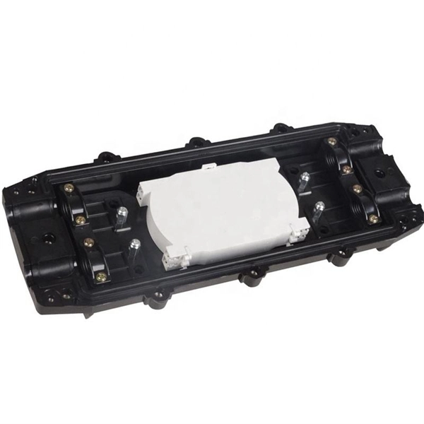
The drop cable connects your home, the patch panel organizes the network, the splice keeps connections seamless, and the optical splitter shares the signal with your neighbors. The fiber drop cable is what makes a true fiber-to-the-home (FTTH) connection possible. It's the final link in the chain that ensures you're getting the full, unfiltered power of fiber internet, not a mix of fiber and older technology. From the street to your living room, every piece of the fiber. To begin, the standard definition of splicing in optical fiber is joining two fiber optic cables together. The other, more common, method of joining fibers is called termination or connectorization. Splicing is most commonly used in the field but has application in cable assembly houses. Infield. In many applications of fiber optics, it is necessary to connect fiber ends (terminations) in some way such that light from one fiber can get into the other fiber without losing too much of its optical power. This creates a permanent and low-loss connection. Both techniques have their advantages and are suited for different applications, but understanding which method to use can greatly impact the network's. Many installations involve splitting the fibers in a cable or dropping a small fiber count cable from a large backbone cable. Backbone cables of 144-288 fibers are common and larger ones are becoming more common too. Drop cables are often only 2-12 fibers, meaning most fibers are continuing.
[PDF]
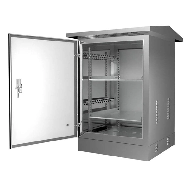
The modern world relies heavily on electrical and communication cables that must be managed and supported across vast distances in commercial and industrial settings. A cable tray is an organized support structure designed to secure and route these insulated electrical cables. In the electrical wiring of buildings, a cable tray system is used to support insulated electrical cables used for power distribution, control, and communication. Cable trays are used as an alternative to open wiring or electrical conduit systems, and are commonly used for cable management in. Whether you're planning a new office setup or upgrading your existing network, the choice of a cable tray system plays a significant role in ensuring the reliability and scalability of your structured cabling solution. It acts as a. en completely installed, without damage either to conductors or structural system use maintain spacing or to keep cables in place when the tray is ect the minimum bend ra-dius for cables as they exit the bottom of the cable tray. A rung spacing of 6 to 9 inches (150 to 230 mm) is preferable when. Explore various cable tray types and sizes for electrical installations. Learn about ladder, perforated, solid-bottom, wire mesh, and channel trays in this complete guide. What is Cable Tray Systems? 1.
[PDF]
A practical, engineering-focused guide to planning and installing underground fiber optic cables with the right cable structure, trench design and protection level for long-life, low-risk networks. Match trench method with the correct underground fiber structure (GYTS . Installing fiber underground is one of the most durable ways to protect a network's backbone — when it's done right. Direct-burial fiber cable eliminates the need for continuous conduit runs and can be faster and more cost-effective on long, open runs. But because the cable sits in soil exposed to. 1. 01 This procedure provides general information for the installation of Prysmian fiber optic cables in direct buried applications. The methods described are intended for guideline use only, as it is impossible to cover all the various conditions that may arise during an installation. Individual. ion) and “ Installed” (after installation). The following formulas may be used to determine general guidelines for installing Corning Optical Communications fiber optic cable; however, refer to the cable specifi simply double the minimum working bend radius. Split cable guides and split 40-in. Fiber optic cable transmits data as pulses of light through thin strands of glass, offering superior bandwidth and distance capabilities compared to traditional copper wiring.
[PDF]