It works on the principle of sensing residual current which is why it is called a residual current device. Nowadays, all domestic and commercial electrical systems and circuits use RCDs. Today, we will see how you can connect an RCD to the distribution . Hey, in this article we are going to see the RCD Wiring diagram and its connection procedure. RCD means Residual Current Device. It is an electrical protective device that protects electrical circuits and devices from some electrical faults such as leakage faults, electrical shock, current. Distribution board is a safe system designed for house or building that included protective devices, isolator switches, circuit breaker and fuses to connect safely the cables and wires to the sub circuits and final sub circuits including their associated Live (Phase) Neutral and Earth conductors. Residual-current devices, commonly referred to as RCDs, are used in many practical applications. They can be found in fuse boxes, electrical switchgears or industrial machine control systems. Therefore. A distribution box uses MCBs, RCDs, and busbars to protect circuits, prevent shocks, and ensure safe power distribution in homes and buildings. This box keeps your home or building safe from electrical dangers. Devices that operate with electricity can cause leakage due to various reasons. If this leakage is not detected and cut off in time, it can lead to.
[PDF]
An optical module is a typically hot-pluggable optical transceiver used in high-bandwidth data communications applications. Optical modules typically have an electrical interface on the side that connects to the inside of the system and an optical interface on the side that connects to the outside world through a fiber optic cable. The form factor and electrical interface are often specified by an int. Electrical Interface TypesThere have been multiple variants of the electrical interface of optical modules that have been used over the years. The earliest forms of optical modules had an analog electrical interface. In the transmit dir. Many different forms of optical modulation and multiplexing have been employed in optical modules. The most common modulation technique historically has been or NRZ. Optical modules have a series of components inside, some of which have received attention from standards development organizations. In many cases, the baud rate of the optical interface do.
[PDF]
The arc extinguishing mode of neutral grounding via arc suppression coil (ASC) is widely used in the distribution network. With the increasing application of active intervention type arc extinguishing device (AIT-A.
[PDF]
EPON means Ethernet Passive Optical Network. It uses fiber-optic cables. These cables give fast and steady internet to homes and businesses. EPON modules play a pivotal role in facilitating fast and reliable data transmission over fiber optic networks, offering enhanced bandwidth capabilities and improved network efficiency. In this step-by-step introduction to EPON modules, we will delve into the basic concepts, various types, benefits. In today's connected world, EPON (Ethernet Passive Optical Network) is a game-changer for delivering blazing-fast internet. This guide dives deep into EPON technology, its benefits over alternatives like GPON, and the critical role of optical modules. Whether you're a network engineer or a tech. A passive optical network (PON) is a fiber-optic telecommunications network that uses only unpowered devices to carry signals, as opposed to electronic equipment. In practice, PONs are typically used for the last mile between Internet service providers (ISP) and their customers. In this use, a PON. At the heart of this evolution are Passive Optical Networks (PON)-built around OLT + ONU/ONT + ODN (splitters)-which enable point-to-multipoint fiber access with excellent cost per user and energy efficiency. It uses only optical fibers to transmit data, voice, and video services. EPON is based on the Ethernet standard and is therefore compatible with most existing.
[PDF]
A firewall is a network security device that separates a trusted internal network from an external network deemed untrustworthy, such as the internet. It regulates incoming and outgoing network traffic based on preset security rules. Here's how firewalls work, their advantages, main types and common applications. Summary: A firewall is a security device that uses a set of rules to monitor and filter network. A Firewall is a network security system, available as hardware or software, that monitors and controls incoming and outgoing traffic based on predefined rules. It acts like a security guard, filtering data packets to either: Accept: Allow the traffic. Reject: Block with an error response. Drop:. Firewalls act as a gatekeeper for network communications examining and filtering network traffic to ensure only authorized and safe traffic passes through. This process protects the network from unauthorized attempts to gain access, cyber attacks, and malicious code. It functions by.
[PDF]
High voltage relays are essential components in electrical systems. They control the flow of electricity in high voltage applications, enabling safe operations. These relays act as switches that open or close circuits. Their design ensures they handle high current levels without. Explore principles and configurations of protective relaying in high voltage systems. Ensure fast, selective fault clearance per IEC/IEEE standards. Protective relaying is the backbone of fault detection and system isolation in As transmission systems grow increasingly complex with integration of. A voltage protection relay system is a necessary component of any electrical setup. It prevents safety hazards and damage to equipment. It monitors voltage to determine if levels rise too high or dip too low. Many industries use voltage protection relay systems, especially those in high-voltage. Eaton's protective relays provide you with unique microprocessor-based devices that eliminate unnecessary trips, mitigate arc faults, protect motors and breakers, and provide system information to help you better manage your system. Our predictive diagnostic solutions include non-destructive testing. In electrical engineering, a protective relay is a relay device designed to trip a circuit breaker when a fault is detected. They are intended to quickly identify a fault and isolate it so the balance of the system continue to run under normal conditions.
[PDF]
Definition of Protective Relay A protective relay is an automatic device that detects abnormalities in an electrical circuit and closes its contacts. This action completes the circuit breaker's trip coil circuit, causing the breaker to trip and disconnect the faulty section from the. Eaton's protective relays provide you with unique microprocessor-based devices that eliminate unnecessary trips, mitigate arc faults, protect motors and breakers, and provide system information to help you better manage your system. Our predictive diagnostic solutions include non-destructive testing. Here, Several circuit breakers in the fault current paths from the generators to the fault location have been tripped. Note that all generators- the power sources – have been disconnected. Therefore, the whole system has gone down, even though many circuit breakers have remained closed. The relay continuously monitors electrical parameters such as current, voltage, frequency, and phase angle. When these parameters deviate from normal operating conditions or. The rectangular devices are test connection blocks, used for testing and isolation of instrument transformer circuits. : 4 The first protective relays were electromagnetic. Protective Relays - Technical Seminar Nov 2016 - Copyright: IEEE 2 Abstract: Protective relays and devices have been developed over 100 years ago to provide “lastline”of defense for the electrical systems.
[PDF]

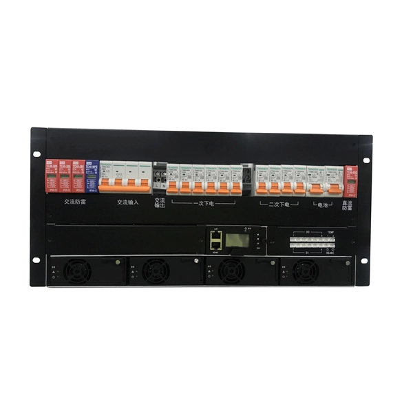
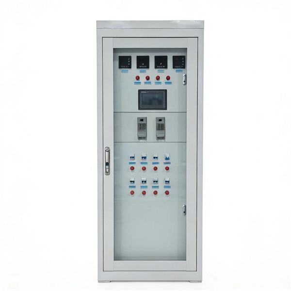
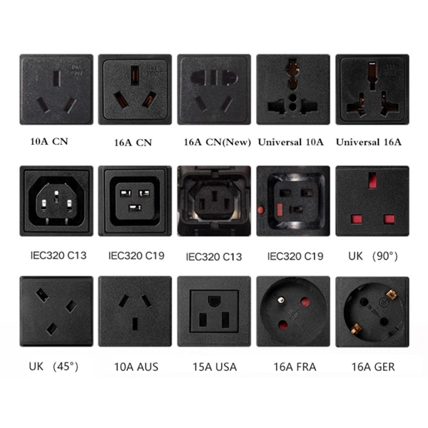
Residual current devices (RCDs) at both the tertiary (equipment-level) and secondary (zone-level) stages. Ensures safe disconnection in case of faults or leakage currents. A distribution box is installed under the main distribution box, and a switch box is installed under the distribution box. These boxes feature bottom entry and exit cables, front-opening doors, and main busbars connected with copper strips for optimal contact. They also include metering systems, ensuring. In a newly constructed residential area, a 10kV power line is introduced into the substation. After stepping down the voltage through the transformer's low-voltage side (0. 4kV), power distribution is achieved through three levels of distribution boxes: the main distribution board, secondary. Equipment inside usually includes isolating switches, circuit breakers, and residual current devices (RCDs). Supplies power to specific buildings or floors. It is specially designed for the special situation of the project construction site and meets the relevant construction power specifications and standards of the. A distribution board (also known as panelboard, circuit breaker panel, breaker panel, circuit breaker, electric panel, fuse box or DB box) is a component of an electricity supply system that divides an electrical power feed into subsidiary circuits while providing a protective fuse or circuit.
[PDF]
Testing is based upon ASTM D4169 “Performance Testing of Shipping Containers and Systems” that is designed to evaluates the ability of shipping units to withstand the distribution environment. Other ISTA test methods can also be performed. When shipping products from one location to another, it's essential to preserve the integrity of its internal contents until it reaches the end user. additional components inside and the product. ” This means that protective packaging. This guide simplifies the landscape of distribution testing standards (primarily ASTM and ISTA), explains the machines you see in a lab, and clarifies who technically “owns” the requirements. Why do we test? (The engineering logic) We test because guessing is expensive. In a distributed supply. CS Analytical is one of the unique service providers that offers Package Distribution Testing in an FDA regulated, cGMP laboratory. This is accomplished by subjecting them to. Micom Laboratories is an ISO 17025 and ISTA-accredited test laboratory for package testing. We help you determine your package's performance under various supply chain stresses such as handling, distribution and transportation. Our testing procedures adhere to several recognized standards.
[PDF]
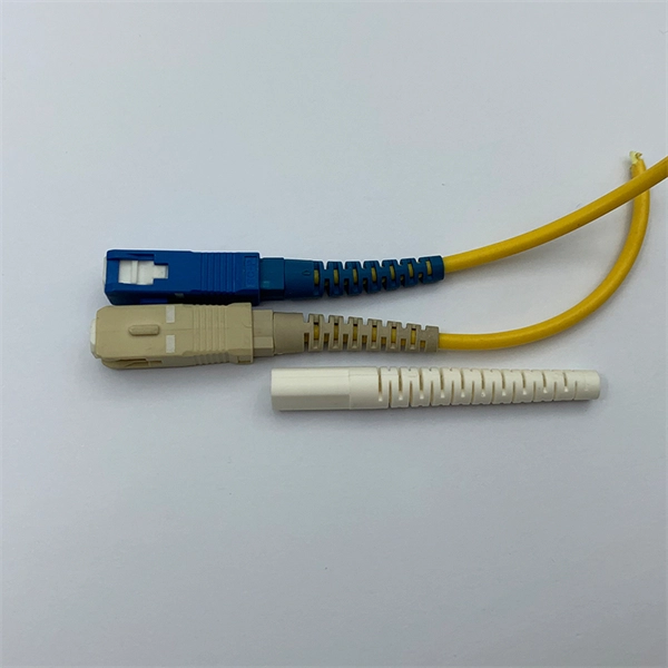
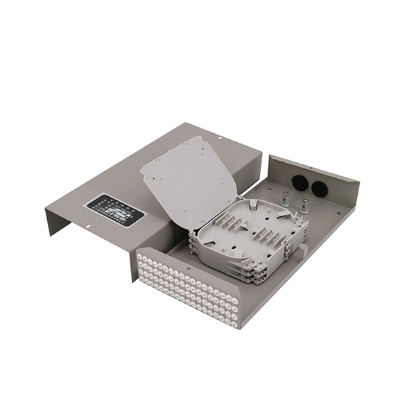
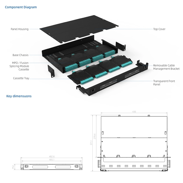
After fiber optic cables are installed, spliced and terminated, they must be tested. Fiber optic testing ensures the performance and reliability of fiber optic networks. As the components like fiber, connectors, splices, LED or laser sources, detectors and receivers are being developed, testing confirms their performance specifications and helps. A structured testing methodology allows engineers and procurement teams to confirm that delivered fiber cables comply with design specifications and international standards. HOLIGHT Fiber Optic applies standardized testing procedures across its passive fiber-optic components to support reliable. Corning Optical Communications manufactures quality flame retardant optical fiber cables for indoor applications, which comply with the requirements of the National Electric Code® (NEC® 2023) published by the National Fire Protection Agency (NFPA). To ensure compliance to these requirements, a. Welcome to NECERO Fiber Optic Cable Factory. In this video, we show the real production line of our fiber optic cables, including material fe.
[PDF]
Fiber testing is the process of verifying the performance of optical fiber cabling. This process includes a range of tests and measurements such as insertion loss, optical return loss, and fiber length. It encompass.
[PDF]