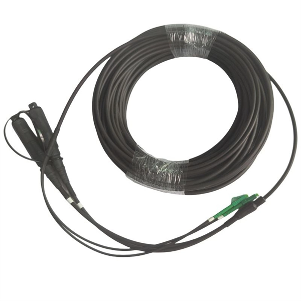
Learn the key difference between pigtail and jumper cables: only one end of a pigtail connects, while both ends of a jumper feature connectors. Similar to coaxial cable, but without mesh shielding, for jumper. When it comes to fiber optics, we naturally think of patch cords and pigtails. Usually people don't know the difference between the two. Let's find out together. Carrier-grade single-mode fiber patch. The Fiber Optic Patch Cord, also referred to as a fiber optic patch cable or fiber jumper, is a specialized cable designed for transmitting data signals using light waves in fiber optic communication systems. It is worth noting that fiber pigtails and patch cords are not the same concept. The main difference between fiber optic patch cords and fiber optic pigtails is that only one end of the fiber optic pigtail has an active connector, and both ends of. Jumper cables and portable jumper boxes are both tools used to revive a vehicle with a dead battery, but they have distinct differences despite sharing a similar end-goal. And with a plethora of purchasable options in both camps, it can be difficult to decide which way to spend your pretty pennies.
[PDF]
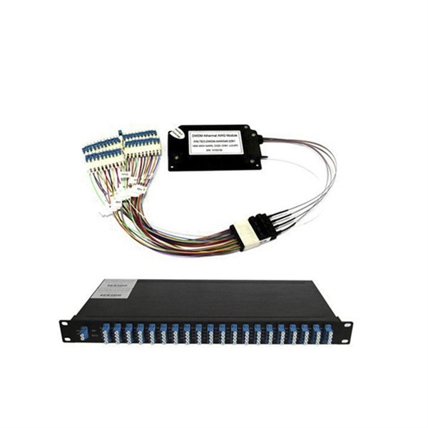
This article provides an in-depth exploration of OSFP copper cable technologies, including DAC, ACC, and AEC, with a focus on 400GB NDR splitter cable applications. Whether the signal is propagated by copper wire, optical fiber, Wi-Fi, or just yelling at the kids down the street, the signal is never as strong at the destination as it is at the source. In the case of physical voice communication, the kids will understand you if they are close-by. If they are. Insertion loss and attenuation are similar concepts, but one is assigned to a single component (insertion loss) whereas the other is assigned to generalized performance (attenuation). Both terms refer to a measurement comparing the signal strength received against a transmitted signal. Standard. Channel Master TV splitters are designed to equally divide the signals on the input port of the splitter to each of the output ports of the splitter. This. Insertion loss is the amount of energy that a signal loses as it travels along a cable link. It is a natural phenomenon that occurs for any type of transmission—whether it's electricity or data. This reduction of signal, also called attenuation, is directly related to the length of a cable—the. In fiber-optic networks like FTTx and PON, PLC splitters are key components for distributing optical signals to multiple users. However, each splitter has complex parameters, including insertion loss, return loss, polarization-dependent loss, and uniformity.
[PDF]
Mouser offers inventory, pricing, & datasheets for Copper Heat Sinks. Check each product page for other buying options. Need help? Copper heatsinks provide efficient heat transfer to keep your electronic components running at optimal temperatures. Discover the perfect cooling solution. Heat sinks are thermal management components designed to dissipate heat from high-power electronic devices and prevent overheating. Their core function is based on the principles of conduction, and convection, transferring heat from a heat source—such as a CPU, power transistor, or BGA package—to. Heat Sinks Cup Clips for TO-5 Case Style Semiconductors, 14. Heat Sinks Cup Clips for TO-5 Case Style Semiconductors, 14. A tariff of 10% may be applied if shipping to the United States. Due to copper's superior thermal conductivity (approximately 400 W/mK, nearly twice that of aluminum), copper heatsinks. Lot Of 2 Dell Copper Aluminum Heat Sink. Pulled From Clean Unit Sold As Scrap 100 PCS (8 Different Sizes) Heatsink Kit with Conductive Adhesive Tape, Alumi. Copper Aluminum Heat Sink Lot Sold As Scrap.
[PDF]
This interactive tutorial explores transmission and reflection of a light beam by three common beamsplitter designs. In addition to the task of dividing light, beamsplitters can be employed to recombine two separate light beams or images into a single path. The tutorial initializes with a cube. The fiber jumper connects the network devices at both ends and is used in the following three scenarios. FC Connector: use a metal sleeve for external reinforcement, fastened with a screw fastener. Generally used in the ODF (the most used on MDF) SC Connector: connected to the GBIC module, its. As title. It is a crucial part of many optical experimental and measurement systems, such as interferometers, also finding widespread application in fibre optic telecommunications. In its. The beam splitter has played numerous roles in many aspects of optics. For example, in quantum information the beam splitter plays essential roles in teleportation, bell measure-ments, entanglement and in fundamental studies of the photon. Electric elds E1 and E2 enter input ports 1 and 2. A beam splitter is an optical device that splits beams (such as laser beams) into two (or more) beams. Beam splitters typically come in the form of a reflective device that can split beams into exactly 50/50, half of the beam being transmitted through the splitter and half being reflected.
[PDF]
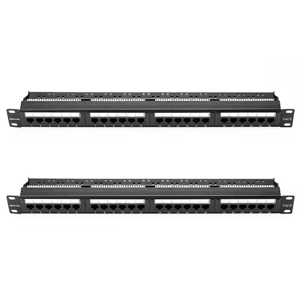
The optical fiber terminal box is usually placed at the end of the horizontal optical cable. The equipment connected by the optical jumper connected from the optical fiber terminal box through the coupler is the closest connection point to the terminal (switching. Some connectors commonly used in optical fiber connection in optical fiber links, such as: optical fiber distribution frame, terminal box, fiber distribution box, ODF distribution frame, what are the differences between them, let's take a look below. The functions of the four connectors can be. It is used in a terminal box to connect the optical fibers in the optical cable, and to connect the optical cable and the jumper through the terminal box coupler (adapter). Jumper Both ends of the jumper are movable connectors, which connect the pigtail and the device. Good quality fiber laying and termination systems help achieve minimal back reflection and low signal loss.
[PDF]
The key to choosing the appropriate one is to understand the theory on which each operates and the application that the attenuator will be applied to. Of course, you also need to be able to determine the attenuator value in decibels required for your application. Later in this article, we will discuss about the various advantages, disadvantages and application of attenuation. What is Attenuation? How Attenuation can be Prevented? What is Attenuation? Attenuation is a term in communication that refers to loss (reduction) in signal strength when a signal is. An optical attenuator, or fiber optic attenuator, is a device used to reduce the power level of an optical signal, either in free space or in an optical fiber. The basic types of optical attenuators are fixed, step-wise variable, and continuously variable. Optical attenuators are commonly used in. Fiber-optic attenuators are a specific type of optical attenuators which are used in fiber optics, e. for achieving a suitable signal level for a data receiver in a telecom system. Usually, such attenuators either have a housing equipped with some type of fiber connectors (e. The attenuator circuit will allow a known source of power to be reduced by a predetermined factor, which is usually expressed as decibels. Signal levels must be strong enough for data interpretation but not so strong as to damage the circuits in the receiver. Excessive fiber optic signal strength exceeding.
[PDF]