Buy CWDM & DWDM Transceiver Modules (SFP/SFP+/XFP, 1270-1610nm, 50/100 GHz Gris, up to 120km) for WDM application at FS. Customized Service on-line. The coarse WDM Module is expanding the bandwidth of Metro/Access Networks. The 4-channel and 8-channel CWDM modules are based on Coarse Wavelength Division Multiplexer devices. They can act as MUX/DEMUX with 20nm channel spacing. It has low insertion loss, low PDL, high isolation and good thermal. The TN-SFP-LX8-Cxxx Series is a cost-effective solution for network modifications and growth. It allows you to use your existing network devices while accommodating changes in your network. The TN-SFP-LX8-Cxxx Series is suitable for a variety of applications, including Gigabit Ethernet switches and. The global market for Coarse Wavelength Division Multiplexing (CWDM) technology, particularly compact modules, is experiencing significant growth. Valued in the billions, the sector is projected to expand at a compound annual growth rate (CAGR) exceeding 12% over the next five years, fueled by. Introduction: Fiberdyne Labs specializes in custom configured, reliable, CCWDM products based on customer requirements. Our low loss Compact CWDM (CCWDM) is based on Free Space Optics & has lower loss and better uniformity versus Thin-Film Filter (TFF) designs. Optional -40°C to 85°C operating.
[PDF]
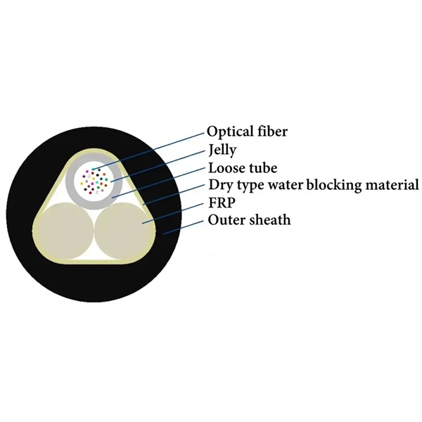
Multi-mode optical modules can only be used for short-distance transmission (SR) due to serious inter-mode dispersion; while single-mode optical modules are mostly used for long-distance transmission such as LR, ER, and ZR. Whether you are in need of single-mode optical modules for lines that require high transmission rates and long distances, or multi-mode optical modules for short-distance transmission scenarios with numerous network nodes and connectors, you can find the optical modules you desire at the LINK-PP. Single-mode fiber uses a 9/125 µm core/cladding structure that supports only one propagation mode, which minimizes modal dispersion and allows signals to travel tens of kilometers with low attenuation. Multimode fibers have larger cores (typically 50/125 µm or 62. Under normal circumstances, the transmission distance of less than 2km is. An optical fiber is a cylindrical dielectric waveguide composed of a central core surrounded by cladding with a slightly lower refractive index. This carefully engineered index contrast confines light within the core through total internal reflection, enabling optical signals to travel with. If your network requires long-distance transmission (over 550 meters), a single-mode optical module is the best choice. For shorter distances, multi-mode modules are more appropriate. Single-mode modules offer higher bandwidth capabilities, making them suitable for high-speed data transmission.
[PDF]
DR4 stands for Datacenter Reach, 4 lanes. PAM4 (4-Level Pulse Amplitude Modulation): This is the predominant modulation technique used in 400G modules. PAM4 allows each symbol to represent two bits of information, effectively doubling the data rate compared to traditional NRZ (Non-Return-to-Zero) modulation 1. Multi-Mode Fiber (MMF):. ✅ What Is a 400G FR4 Optical Module? A 400G FR4 optical module is a type of Ethernet transceiver designed for high-speed data transmission over single-mode fiber with a reach of up to 2km. It implements the 400GBASE-FR4 standard defined by IEEE 802. "SR" stands for "Short Reach," supporting a maximum. QSFP-DD stands for Quad Small Form Factor Pluggable – Double Density. Defined by the QSFP-DD MSA group, it is a high-speed, hot-pluggable form factor crucial for high-density networking in the optical communication industry. As the optimal form factor for 400G optical transceivers, QSFP-DD enables. QSFP-DD, an abbreviation of Quad Small Form-factor Pluggable (QSFP) – Double Density (DD), is a high-speed hot pluggable form factor defined by the QSFP-DD MSA group as a key part of the optical communication industry to achieve high-density networking.
[PDF]
The optical module is the foundation of optical communication that provides photoelectric conversion (see Figure 2). The photoelectric conversion efficiency of optical modules is crucial, and it directly affects the quality and performance of optical communications. From the technical level, HISILICON makes improvements. These two products are part of the LIGHTPASS ® Series active optical modules expected to be used for optical interconnection applications and IOWN* structures used for data centers and other uses. Demo kits for evaluating these products will be available from September 2023, and mass production is. Microwave photonics technology (MWP), which has been applied to various radar, Telcom, Electronic Warfare systems, is now facing more and more challenging development trend of miniaturization and modular array for increasing node counts and system complexity. In the context of data communication, it involves transforming data into light pulses for transmission through optical fibers and converting received light signals back into electrical. The optical module is the key device in all the links of this circulation process (see Figure 1). Two modules are used in pairs. The radio-frequency signal.
[PDF]
Description: Explore how optical modules enable high-speed data conversion across data centers, 5G networks, storage systems, and WDM applications. Learn about SFP, SFP28, CWDM, and DWDM solutions. Optical modules are widely used in various industries. Aerech Networks will use this article to introduce you to the application scenarios of optical modules. Optical modules are critical components in modern data communication, serving to convert electrical. Optical module is mainly used in the field of data communication. Its function is to realize the mutual conversion of photoelectric signals. Due to the rise of big data, blockchain, cloud computing, Internet of things, artificial intelligence and 5G, data traffic has increased rapidly. As the demand for faster and more reliable internet and data services grows, understanding these devices becomes increasingly important. This guide will explore. What You'll Learn in This Guide By reading this article, you will: By the end, you'll have a clear, expert-level understanding of CFP optical modules—and more importantly, the confidence to decide whether they are the right fit for your specific application.
[PDF]
800G optical modules provide 2× bandwidth and ~30–40% better power efficiency per bit than 400G, while reducing fiber count significantly. However, 400G remains more cost-effective for enterprise workloads, and 1. 6T is still in early deployment stages primarily targeting AI-scale data. 400G, 800G, and 1. 6T is growing exponentially. This surge is driving technological upgrades in optical modules toward higher data rates. NADDOD, the leading optical modules. Developments in three distinct areas are needed for 800G deployment: optical modules and direct attach copper (DAC) cables, switch ASICs, and 800GE standardization. Not all these need to be fully delivered for data center operators to benefit from 800G upgrades. By understanding the key. Choosing between 400G and 800G optical modules depends on your workloads, scale, and budget. This guide breaks down the differences, use cases, and deployment advice in simple but detailed terms. What are Optical Modules? An optical module (or optical transceiver) is a pluggable device inserted. Today's data center Ethernet switches are essentially optical communication devices, as the entire system operates on optical transmission principles. This article will explore the evolution of modules' speed and form factor from 400G to 1.
[PDF]
The Base Station Optical Module Market was valued at USD 1. 2 billion in 2024 and is projected to reach USD 3. 5 billion by 2034, registering a CAGR of 11. The global market for Base Station Optical Module was valued at US$ million in the year 2024 and is projected to reach a revised size of US$ million by 2031, growing at a CAGR of %during the forecast period. It is composed of optoelectronic devices, functional circuits and optical interfaces. In this report, we will assess the current U. tariff. Base Station Optical Module by Application (Macro Base Station, Micro Base Station), by Types (Optical Receiver Module, Optical Transmitter Module, Optical Transceiver Module), by North America (United States, Canada, Mexico), by South America (Brazil, Argentina, Rest of South America), by Europe. Product Type Outlook (Revenue, USD Million, 2024 – 2034) ( Transceivers, Optical Amplifiers, Optical Switches, Others), Application Outlook (Revenue, USD Million, 2024 – 2034) ( Telecommunications, Data Centers, Enterprise Networks, Others), End-Use Outlook (Revenue, USD Million, 2024 – 2034) (. Base Station Optical Module Market report includes region like North America (U. S, Canada, Mexico), Europe (Germany, United Kingdom, France), Asia (China, Korea, Japan, India), Rest of MEA And Rest of World.
[PDF]
An optical module is a typically hot-pluggable optical transceiver used in high-bandwidth data communications applications. Optical modules typically have an electrical interface on the side that connects to the inside of the system and an optical interface on the side that connects to the outside world through a fiber optic cable. The form factor and electrical interface are often specified by an int. Electrical Interface TypesThere have been multiple variants of the electrical interface of optical modules that have been used over the years. The earliest forms of optical modules had an analog electrical interface. In the transmit dir. Many different forms of optical modulation and multiplexing have been employed in optical modules. The most common modulation technique historically has been or NRZ.
[PDF]
This comprehensive guide breaks down the internal structure, core components (TOSA, ROSA, lasers), and operational mechanisms of SFP optical modules, enriched with technical insights and real-world applications. As an essential component of optical fiber communication, optical modules are optoelectronic devices that facilitate the conversion between optical and electrical signals during the transmission process. Optical Modules (also known as Optical Transceivers) are critical components in fiber optic communication systems. This assembly comprises a light source, such as a laser diode or a semiconductor light-emitting diode (LED), an optical interface, a. Whether you're selecting an optical transceiver module for short-range multimode applications or long-haul coherent transmission, understanding these parameters ensures reliability and performance. We'll cover everything from physical form factors to spectral characteristics, modulation formats.
[PDF]
A Thin-Film Filter (TFF) is an optical device that uses multiple layers of dielectric coatings deposited on a substrate to selectively transmit or reflect specific wavelengths of light. It is a fundamental component in modern optical communication systems. The Z-Block is a core optical component used in wavelength division multiplexing/demultiplexing (WDM) systems. Structurally, it is typically composed of several integrated optical elements, including collimating lenses, rhomboid prisms, and specially designed optical mirrors. TFFs are widely used as. The Process Technology of Optical Coating: Applications of TFF in Optical Communication Optical coating technology has revolutionized the way we enhance the performance and durability of optical devices, particularly in optical communication systems. As the demand for high-speed internet and. WDM (Wavelength Division Multiplexing) is a technology that expands the optical fiber transmission bandwidth and improves network transmission capacity by transmitting multiple optical signals of different wavelengths in the optical fiber. TFF (thin film filter) and AWG (arrayed waveguide grating). A thin film resonant cavity filter (TFF) is a Fabry-perot A cavity is formed by using multiple reflective dielectric thin film layers. The TFF works as bandpass filter, passing through specific wavelength and reflecting all other wavelengths. The cavity length decides the passing wavelength.
[PDF]
Two fiber ports (TX and RX) side-by-side. Simplex LC: single fiber port. Used for BiDi (Bidirectional) modules where data is sent and received on the same strand using different wavelengths. SFP (Small Form-factor Pluggable) is a compact, hot-pluggable network interface module used to connect network devices (switches, routers, firewalls) to fiber optic or copper cables. Think of it as the “translator” for your network equipment, converting electrical signals into optical signals. The optical module serves as a crucial component in optical fiber communication systems, operating at the physical layer, which is the lowest layer in the OSI model. Its primary function is to achieve optoelectronic conversion by converting electrical signals into optical signals and vice versa. An. An optical module is mainly composed of optoelectronic devices (including the optical transmitter and optical receiver), functional circuitry, and optical interfaces. Optical modules typically have an electrical interface on the side that connects to the inside of the system and an optical interface on the side that connects to the outside. Whether you're selecting an optical transceiver module for short-range multimode applications or long-haul coherent transmission, understanding these parameters ensures reliability and performance.
[PDF]
iPronics is unveiling a dedicated manufacturing line for the packaging, assembly, testing, and qualification of its ONE Series SiPh OCS, enabling volume production from wafers to line cards that integrate into the customer's rack. The EXALOS Hybrid Optical Packaging Platform (HOPP) is a packaging technology that has been developed and used since 2008 for realizing advanced optical modules with miniature components (millimeter-size or smaller) that are aligned and assembled with micron-level or even sub-micron precision. The. ficonTEC provides device micro-assembly and testing solutions for the photonic device industry. These solutions are realized as cutting-edge, high-precision production systems utilizing advanced automation approaches, regardless of the device material and target application. Our modular system. VALENCIA, Spain, March 17, 2026 (GLOBE NEWSWIRE) — iPronics, the leader in programmable silicon photonics (SiPh) for AI datacenter networking, today announced a major expansion of its global manufacturing capability through a deepened partnership with Fabrinet (NYSE: FN), a world-class, Tier 1. SEMIPHOTON, INC. together with our manufacturing Partners, offers state-of-the-art fully-automated and semi-automated Solar/PV modules production lines, designed to fit any capacity and factory size.
[PDF]
It is designed to maximize the capacity of fiber-optic cables by simultaneously transmitting multiple data signals on the same fiber using different light wavelengths. The fundamental principle of WDM is rooted in the properties of light and fiber-optic cables., colors) of laser light. This technique enables bidirectional communications over a. Wavelength Division Multiplexing (WDM) is a technology that allows network operators to multiply the data-carrying capacity of existing fiber optic lines. The concept involves sending multiple independent data streams down a single strand of fiber, much like transforming a single-lane road into a. ptical multiplexing techniques, wavelength division multiplexing (WDM). The chapter begins with a quick historical account of the origin of optical communication and its exponential growth following the invention of erbium oped fiber amplifier (EDFA) leading to the widespread adoption of WDM. This guide delves into the principles, types, applications, and future trends of WDM. Wavelength division multiplexing is a method of modulating multiple signals at different wavelengths (channels) to transmit them on a single waveguide or fiber. To begin with, we assume that we have the element.
[PDF]
In fiber-optic communications, wavelength-division multiplexing (WDM) is a technology which multiplexes a number of optical carrier signals onto a single optical fiber by using different wavelengths (i.e., colors) of laser light. This technique enables bidirectional communications over a single strand of fiber (also called wavelength-division duplexing) as well as multiplication of capacity. The. SystemsA WDM system uses a at the to join the several signals together and a at the to split them apart. With the right type of fiber, it is possible to have a device that does both s. Originally, the term coarse wavelength-division multiplexing (CWDM) was fairly generic and described a number of different channel configurations. In general, the choice of channel spacings and frequency in these co.
[PDF]
When a long-distance module transmits signals over relatively short distances—or when the receiver is too close to the transmitter—the intense optical signal may directly saturate the receiver's optical detector. Optical Modules (also known as Optical Transceivers) are critical components in fiber optic communication systems. As the core optoelectronic devices operating at the Physical Layer of the OSI model, their primary function is to perform electro-optical and photo-electric conversion during signal. As an essential component of optical fiber communication, optical modules are optoelectronic devices that facilitate the conversion between optical and electrical signals during the transmission process. This is not an arbitrary adjustment but a necessary measure, carefully implemented based on signal transmission principles, device specifications, and practical. Optical Signal Attenuation is the single greatest factor limiting the distance and performance of your network. Understanding it is crucial for anyone involved in data centers, telecommunications, or enterprise networking. This guide will demystify signal loss, explore its causes, and show you how. In the field of optical fiber communication, the attenuation operation of long-distance modules is one of the key links to ensure the stable operation of the communication system. This operation is not carried out arbitrarily, but is a necessary measure after comprehensive consideration of many.
[PDF]