In this tutorial, we will learn how to use the DHT11 sensor module with the Micro: bit V2 board. This sensor can measure temperature and humidity; we'll display these measurements on an LCD screen. Also, I have used the Microsoft MakeCode platform to write our code. Welcome to the class on making a temperature and humidity detection device! This project uses a micro:bit board, OLED display, and temperature-humidity sensor connected via the IIC interface of the Petal Base Expansion Board to achieve real-time detection and display of environmental temperature. In this tutorial, we will learn how to use the DHT11 sensor module with the Micro: bit V2 board. MakeCode is great because it. Imagine monitoring real-time temperature, humidity levels, atmospheric pressure, rainfall detection, air quality index (AQI), and more—right from your local network. With the power of the Arduino UNO R4 WiFi, you can create a dynamic weather dashboard web page that displays all your environmental. This project is a smart weather station built using the ESP8266 microcontroller integrated with multiple environmental sensors — BMP180 for pressure and altitude, DHT11 for temperature and humidity, and MQ135 for air quality monitoring. It continuously collects real-time weather data and air. This tutorial is all about Humidity & Temperature Monitoring with DHT11 & STM32 Microcontroller. There is a dht module that comes with the MicroPython firmware by default.
[PDF]
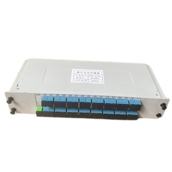
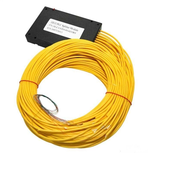
This paper aims to study the design, simulation, and optimization of low-loss Y-branch passive optical splitters up to 64 output ports for telecommunication applications. For a waveguide channel profile, the standard material silica-on-silicon is used. Two important technologies for optical layer monitoring are Optical Performance Monitoring (OPM) and Optical Power Detection (OPD). Although they aim to maintain network health, they differ significantly in scope, technique, and deployment. This article delves into these differences, equipping. Optical Performance Monitoring (OPM) is considered a necessity over an optical network to enable sensibility of traffic line status and attain outstanding Quality-of-Service (QoS). The Y-splitters are designed and simulated at. Passive optical networks (PONs) are the network architecture of choice for residential fiber deployments. A PON is designed specifically to be cost-effective for delivering high data-rates to large customer populations. signals and various components of OPM functionalities are indispensable robust network operation and plays a key role flexibility and improve overall. Optical performance monitoring (OPM) is used for managing high capacity dense wavelength-division multiplexing (DWDM) optical transmission and switching systems in Next Generation Networks (NGN). OPM involves assessing the quality of data channel by measuring its optical characteristics without.
[PDF]
By combining compact laser sources with sub-1 ml volume and ultrastable optical cavities, this work enables extremely compact and robust ultrastable laser systems with applications in low phase noise microwave generation, sensing, and satellite ranging. The Laser Light Screen System faces critical technical challenges in high-speed, long-range target detection: when a target passes through the light screen, weak light flux variations lead to significantly degraded signal-to-noise ratios (SNRs). Traditional signal processing algorithms fail to. Ultra-low-noise microwave signals play a driving role in the development of modern scientific technologies such as radar, communication, and sensing. On-chip photonic integration provides an attractive approach for the implementation of ultra-low-noise microwave signal sources with attractive added. We demonstrate thermal-noise-limited direct locking of a semiconductor distributed feedback (DFB) laser to a sub-1 mL volume, ultrastable optical cavity, enabling extremely compact and simple ultrastable laser systems. Using the optoelectronic laser locking method, we realize over 140 dB. Here we address these shortcomings with a hybrid optoelectronic approach that combines simplified optical frequency division with direct digital synthesis to produce tunable low-phase-noise microwaves across the entire X-band (8–12 GHz). Traditional signal processing algorithms.
[PDF]
On the US market, a 5. 26 mm 2 (10 AWG) ground wire must be used, and in all other markets a 6 mm 2 must be used. Grounding of the units: Attach a ground wire from one of the threaded studs (A) at the bottom of the housing, to the mounting plate (B). Attach a second grounding wire from the mounting. The correct connection method of Distribution box grounding wire mainly includes the following steps: 1. Find the grounding bar or PE bar Open the distribution box and find the position marked with the grounding plate or PE letter. The basic rule achieves this through an equipment grounding jumper; four exceptions. An equipment grounding conductor passing through the box without a splice is not required to be joined inside the box to others that are spliced in the box. 148 addresses the continuity of equipment grounding conductors and their attachment in boxes. Not all boxes are metal or provide. Correct grounding of services depends upon understanding the definition and role of the grounded conductor. The neutral conductor is typically the grounded conductor connected to the system's neutral point, carrying current under normal operation. Whether you're a seasoned pro or just starting out, this comprehensive guide will give you practical.
[PDF]
Please view our full RLH price list and contact us at info@fiberopticlink. com if you have any questions or special project needs. A fiber optic distribution panel (also known as a fiber distribution frame or FDF) serves as a centralized hub for managing, terminating, and distributing fiber optic cables in telecommunications and data networking systems. Fiber Adapter Panels fit all Multilink rack and wall mount Fiber Distribution Units. Panels are available in Simplex or Duplex adapter format. Patch panels are integral components of any network system. This equipment helps keep data systems and server rooms organized, functional and easily. Fiber optic patch panels are designed either to support direct termination or fusion splicing of the optical fibers. Fiber optic patch panels allow the optical splices of the fiber. Belden offers clean, simple, and lightweight Wall-Mount Panels within its DCX, FiberExpress (FX) UHD and ECX ecosystems. The versatile DCX Zero-U wall-mounting devices hold DCX cassettes and adapter frames and can be mounted under standard cable basket trays. The FX UHD and ECX modular platform of. UnitekFiber offers a wide variety of wall mounted fiber optic enclosures, including indoor fiber optic enclosures, outdoor rated fiber optic enclosures, plastic fiber optic enclosures or metal fiber optic enclosures. The wall mount fiber enclosure, also known as a wall mount fiber patch panel, is a.
[PDF]
This manual is valid for the Meter Connection Box from hardware version A and firmware version 1. This manual is intended for installers. DANGER! DANGER indicates a hazardous situation which, if not avoided, will result in death or serious injury. WARNING!. ith solar inverters, solar string monitor-ing systems provide all the information needed for transparent monitoring of the enerated power. The current level of each string is collected by the string monitoring system, which is installed inside of combiner boxes. Those combiner boxes are first. Connecting solar panels to monitoring systems is essential for optimizing the performance and efficiency of solar installations. Identify the type of monitoring system needed, 2. Regularly update and manage. t de functie v ge sense cable for starter battery. y isolation (available separately). Operated by control on System Panel. The combiner box monitoring system provides monitoring and management for each device in a solar power generation system. It can monitor the status of surge protectors and circuit breakers without an external power supply. It provides features required to maintain loads such as: Select a topic to jump to that page.
[PDF]
This paper builds a network platform based on wireless transmission technology to realize the intelligent monitoring of equipment operation status and energy efficiency monitoring in the current oilfield well and inter station well pads. Accurate prediction of electricity consumption in crude oil pipeline transportation is of significant importance for optimizing energy utilization, and controlling pipeline transportation costs. Currently, traditional machine learning algorithms exhibit several limitations in predicting electricity. Since monitoring systems in long-distance infrastructures may benefit from solutions based on multi-hop communication, we consider oil pipeline infrastructures in the Saudi Arabian desert as a case study. An analytical model is considered for estimating the above-stated parameters and evaluating. ABB's Control Room offering includes a comprehensive range of solutions designed to optimize the operator workspace for critical 24/7 processes across various industries. The control room is considered one of the most critical areas in any facility, impacting daily decision-making and overall. In an era where energy is not just a commodity but a cornerstone of modern enterprise, an EMS (Energy Management System) power system heralds a revolution in how organizations engage with their energy resources.
[PDF]
With key (included) turn the Earth lock clockwise (Fig 1). The Earth cover will pop open. Take the Earth cable end connector (not included) and plug into the Earth socket. The Powersafe connectors are mechanically keyed to prevent connection errors. In this video, the entire power distribution box is removed including electrical connections on the bottom. Enjoy kind human being of planet Earth. As for the opening of the equipment and the connection, see PDU INSTALLATION MANUAL (downloaded from www. This manual is developed for the. duct, please dispose the pro ormal operation due to poor manufacture quality. A paid repair will be provided if the warranty period expires. For any damage due to one of the following situations, a paid repair duct, please dispose the pro ype, a “R” is added after the Specification. It takes power from one source and spreads it out. PDUs are very important for managing power well. They are used in places like data centers and server rooms. 6 Earthing of power distribution box (optional) position, or to the green display (2) (dependent on the protective element). Close the inspection window. Ensure all connections are tight and secure. Look for any signs of burnt or damaged wiring. Testing Test the grounding system.
[PDF]
Provides accurate and cost-effective testing methods for the optoelectronic signal testingand anomaly simulation of high-speed optical transceiver modules. The OptoBERT™ OPB04X10 is the industry's most compact, cost-effective, easy-to-use 4-channel 10Gbps electrical bit-error-ratio tester (BERT). PBT3058 is a high-performance Bit Error Ratio Tester which can be used for physical layer characterization and consistency test of high-speed serial signal. 6TBASE/CEI-224G standards and also supports PCIe rate testing ranges through extended rate. Transmitter net measurement:. Our portable and stationary provers ensure accuracy and industry compliance for flow meters on a variety of in the field applications. Available in custom configurations and max flow rates, each prover is designed to eliminate the many prover problems of the past including our Unidirectional. In high-speed digital communication systems, even the smallest bit-level error can compromise performance, reduce efficiency, or lead to costly rework. That's why Physical Layer Tech offers precision-engineered Bit Error Rate Testers (BERTs) designed to verify data transmission accuracy and ensure. Whether you are looking for the smallest handheld 100G bit error rate tester in the world for your field job, or perhaps your needs take you into the lab, VIAVI has you covered with our accurate and easy-to-use BERT equipment for any use case. · Use control board and replaceable.
[PDF]
This guide highlights five top-rated options, detailing their tech specs, durability, and ease of use. Each entry provides a quick overview so you can compare sizing, IP ratings, and mounting features before choosing. Limitations of “Dumb” Waterproof Boxes + “Smart” Indoor Switches: Many attempt to achieve outdoor automation by placing an indoor smart switch inside a generic waterproof outdoor electrical box. This creates several problems: —Signal Degradation: The metal or thick plastic of the outdoor box can. We specialize in creating custom NEMA enclosures tailored to your exact needs. Browse our durable lineup of outdoor electrical enclosures designed to protect sensitive components from rain, dust, UV exposure, and harsh environmental conditions. Built for rugged reliability, these enclosures are. Exterior electrical boxes are weatherproof enclosures that protect outdoor electrical connections from moisture, dust, and impact damage. Here's what you need to know: Key Features to Look For: Top Applications: Whether you're adding a new outdoor outlet for holiday lights or upgrading an existing. Discover the 5 best outdoor electrical junction boxes for weatherproof protection. Compare features, materials, and ratings to ensure safe, code-compliant installations. When you're running electrical wiring outdoors, proper protection isn't optional—it's essential for safety and code compliance. Each option balances.
[PDF]
This white paper introduces an evolved methodology to manage FTTx Optical Distribution Network (ODN) performance. A centralized OTDR-based solution is the core of this evolved methodology, which greatly improves the visibility and operation efficiency in maintaining ODN . In recent years, optical network systems have doubled their information rate using a new multiplexing technique known as the Orbital Angular Momentum (OAM) of light, which gives signal carriers additional freedom. By utilizing new, sophisticated modulation formats and various access strategies. ODN footprints are exploding with FTTx, 5G back/fronthaul, and data-center access. Traditional maintenance—handwritten labels, scattered spreadsheets, and single-purpose tools—struggles with slow fault localization and unreliable records. On a. EXFO's remote fiber testing & monitoring solutions are built based on fixed OTDR test equipment placed at strategic central locations across the network. The condition of fiber optic installations are constantly checked and the locations of degradations or breaks are pinpointed within minutes of. The architecture of an optical distribution network (ODN) plays a pivotal role in determining the cost, scalability, and operational efficiency of PON and FTTx deployments. From dense urban builds to remote rural rollouts, this article compares three fundamental ODN structures to guide the design.
[PDF]
It describes the data switch that is located at the network's backbone or physical core. So that it can act as the gateway to a wide area network (WAN) or the Internet, it must be a high-capacity switch. There are different types of enterprise switches that perform various roles in these layer-based or hierarchical ethernet networks. The hierarchy Ethernet network. The HPE Aruba Networking Campus leverages advanced technology to deliver a modern, agile con-nectivity platform that meets the needs of organizations of any size, with distributed or centralized operations. The HPE Aruba Networking AOS-CX operating system applies consistent common switching. Core switches and edge switches are two essential components that play distinct roles in the functioning of a network. This article explores what they are and how they differ. What is a core switch? How do we choose the right core switch? Do you have such. For smaller deployments, the goto Cisco configuration is a pair of 4500-X switches in a VSS configuration with 2960-X switches for access layer. The VSS allows two switches to be managed as one, but if a switch fails then the other can pick up seamlessly. They perform a vital function in ensuring the network's reliability and stability because they are in charge of routing data across the network infrastructure in a reliable and timely manner.
[PDF]
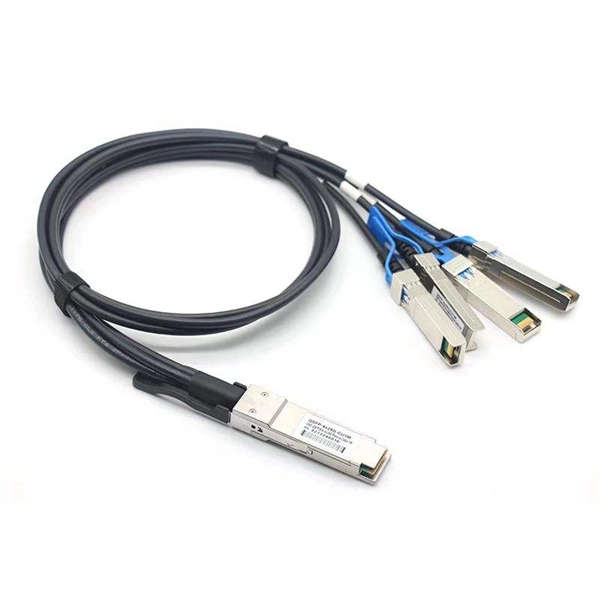
It performs error detection and alarm monitoring, serving as an essential tool for bit error testing in R&D and production of optical modules/ devices. Bit Error Ratio Tester is an instrument used to test and analyze bit error ratio in digital transmission systems, fiber optic communication systems, and digital microwave communication systems. Dimension Technology's BERT800 bit error tester series offers a comprehensive solution for testing and verifying high-speed optical transceiver modules. OPTELLENT is a provider of broadband test and measurement solutions for communications. The Company's test & measurement solutions are used in product development, manufacturing. As transmission rates continue to accelerate, accurately measuring bit error rates in optical modules is crucial to ensure reliable performance. There are three interchangeable slot boards which include QSFP, SFP+ and SFP ports separately. QSFP, SFP+ and SFP ports follow QSFP MSA, SFP+ MSA and SFP MSA. The user interface allows you to individually monitor bit error rate, error count and timer by connecting to PC via USB cable. In high-speed digital communication systems, even the smallest bit-level error can compromise performance, reduce efficiency, or lead to costly rework.
[PDF]