Our CAD drawing files are available as . STP files for download. Discover Autodesk Revit's RVT format for our T&B cable tray BIM files. With its intuitive interface and robust features, Revit streamlines design, offering enhanced customization. Access and download T&B cable trays Revit files for free now! Find and download Intergraph Smart 3D CAD VUE files for. Our CAD drawing files are available as. Discover all CAD files of the "Cable trays" category from Supplier-Certified Catalogs ✅ SOLIDWORKS, Inventor, Creo, CATIA, Solid Edge, autoCAD, Revit and many more CAD software but also as STEP, STL, IGES, STL, DWG, DXF and more neutral CAD formats. can access every toolset, what can you do that you couldn't do before? Do you know that you can use AutoCAD MEP software to create cable tray, hanger, conduits pipe fitting, and MvParts that you can use in AutoCAD Plant 3D software? Getting started with the parametric parts can intimidate a new. Tray installation details for the location of a project's electrical wiring; in addition to blocks with different angles that allow the wiring circulation to be identified. Free CAD and BIM blocks library - content for AutoCAD, AutoCAD LT, Revit, Inventor, Fusion 360 and other 2D and 3D CAD applications by Autodesk. You can exchange useful blocks and symbols with other CAD and BIM users.
[PDF]

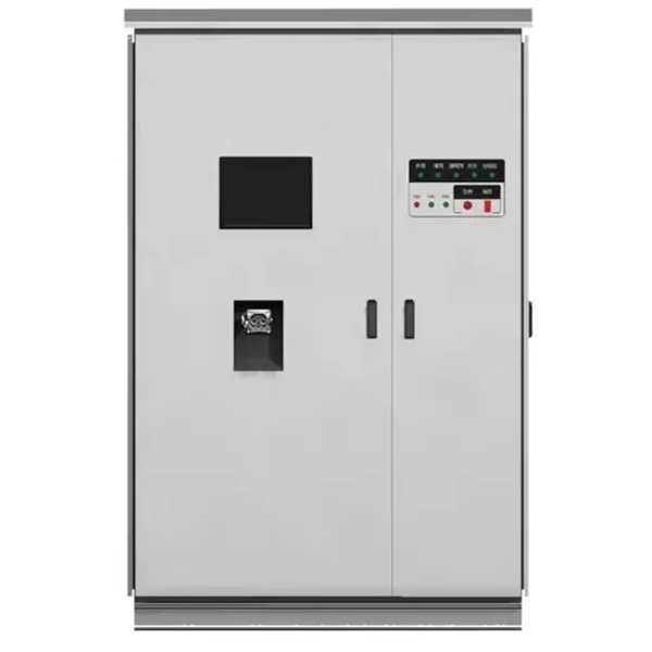
The Box Fill Calculator is an essential electrical installation tool that determines the maximum number of conductors, devices, and fittings that can be safely installed in electrical boxes according to National Electrical Code (NEC) standards. Plan devices by location with clear gang strategies and packing options built‑in. Enter outlets, switches, low‑voltage, fans, and junctions per space including spare allowance. Auto‑pack calculates 4‑, 3‑, 2‑gang mixes, minimizing wall clutter and box count. Instantly see totals per room and. Calculate electrical box fill capacity and ensure NEC compliance for proper wire management and electrical safety. Calculate electrical box fill per NEC 314. 16, including conductors, devices, clamps, and grounding. Ensure your installations are safe and code-compliant. 16 mandates these calculations to prevent overcrowding, which can. It takes the incoming power and safely distributes it to different circuits throughout your building. Whether in a home or an industrial facility, this box keeps your electrical setup organized, functional, and efficient. However, the key to a safe and reliable system lies in proper installation.
[PDF]
This calculator provides the calculation of the total frequency bandwidth used by a WDM system. Calculation Example: The total frequency bandwidth used by a WDM (Wavelength Division Multiplexing) system is calculated based on the number of channels, the channel spacing, and any guard. Calculate wavelength division multiplexer (WDM) system parameters including wavelength spacing, total bandwidth, spectral efficiency, system capacity, and frequency range. WDM allows multiple data channels at different wavelengths to be transmitted simultaneously over a single optical fiber. In fiber-optic communications, wavelength-division multiplexing (WDM) is a technology which multiplexes a number of optical carrier signals onto a single optical fiber by using different wavelengths (i., colors) of laser light. This technique enables bidirectional communications over a. Wavelength Division Multiplexing (WDM) is a technique in fiber-optic communication systems that enables multiple optical signals with different wavelengths to be combined, transmitted, and separated over a single optical fiber. To begin with, we assume that we have the element. Wavelength multiplexers and demultiplexers are needed in order to be able to use wavelength division multiplexing. The chapter begins with a quick historical account of the origin of optical communication and its exponential growth following the invention of erbium oped fiber amplifier (EDFA) leading to the widespread adoption of WDM.
[PDF]
This study aims to develop a simple yet efficient performance-based design optimization methodology for cable tray systems in building structures. In the paper, the drift ratio between adjacent supports i.
[PDF]
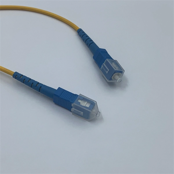
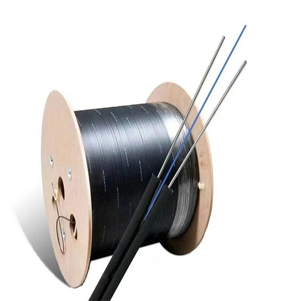
The normal recommendation for fiber optic cable is the minimum bend radius under tension during pulling is 20 times the diameter of the cable (d). This includes pulling tension, minimum bend radius or diameter and crush loads. Installers must understand these specifications and know how to install cables without. The correct bend radius calculation is a fundamental prerequisite for high-quality fiber optic installations and is decisive for long-term network performance and reliability. Why Use. Check safe bend radius, loop clearance, and slack for racks, risers, conduits, and storage coils before you route the fiber. The calculator uses conservative routing multipliers, then compares the actual bend radius against the cable family minimum so you can spot risky turns early. Configuration. Key Takeaway: Bend Radius is the minimum curve a cable can handle without damaging its internal structure or degrading the signal. Maintaining the integrity of your network requires more than just high-quality hardware; it demands precise installation. Cable bend radius is the critical threshold. Professional bend loss calculator for optical fibers. Analyze macrobending and microbending losses, determine critical bend radius, and optimize fiber routing for laser delivery systems and communication applications.
[PDF]
Free electrical load calculation tool for residential and commercial buildings. Calculate service entrance sizing, panel loads, demand factors, and ensure NEC Article 220 compliance. A sub panel is a secondary distribution point, fed from the main service panel, that provides a local hub for additional circuit breakers and wiring. Always verify calculations with a. The NEC (National Electrical Code) provides guidance on how to size wires correctly for feeders and subpanels. These rules change slightly from one edition to the next. This guide focuses on NEC 2023 standards. Choosing the correct subpanel wire size ensures safety, prevents overheating, and keeps. How to Size a Subpanel or Main Lug? For load calculation, multiply continuous loads (lasting 3 or more hours, e., water heaters) by 125% per NEC 310-14 and add 100% of non-continuous loads (like light bulbs, TVs). Total Load = 125% * Continuous Loads + 100% * Non-Continuous Loads To account for. URD cable, short for Underground Residential Distribution Cable, is a type of low-voltage power cable used in secondary power distribution networks. to by meter, Legacy the size is sizes sized of the include based main 60A on breaker. Common of The the main meter sizes breaker. socket, When main impacting new residential legacy breaker, knob electrical loads are added, available capacity.
[PDF]
Professional home circuit calculator per NEC Article 210 and 220. Determines the total number of branch circuits, wire sizes, breaker ratings, and GFCI/AFCI protection requirements for residential electrical systems. Covers general-purpose lighting circuits, small appliance circuits, laundry. Before determining the required number of circuits and associated calculations, let's define and differentiate between branch circuits, general-purpose lighting branch circuits, and individual branch circuits. According to NEC Article 100 – Definitions: Branch Circuit: Refers to the conductors. Before we dive into calculations, let's get familiar with a few essentials: 1. Your Project's Total Power Demand This isn't just adding up wattages randomly. Think of your home as a busy kitchen—not every appliance runs at once. Do you really need the hair dryer, microwave, and vacuum running. Professional electrical panel schedule tool for creating detailed load distributions, calculating circuit loads, balancing phases, and ensuring NEC compliance for electrical distribution panels. Panel schedules are essential for electrical system documentation, load analysis, and NEC compliance. Compute the branch circuits, feeders, service-entrance conductors, and wire protection. How do you determine the minimum number of general lighting and general-use branch circuits required by the NEC for dwellings? A.
[PDF]
