Use this worksheet to input values for all variables that will impact your system's performance. After entering your values, please ensure you click the 'Calculate Link Loss' button at the bottom of the page to generate your total link loss. Add connectors, splices, bends, and safety margin easily. See results instantly above the form, then adjust values. Choose a mode, then enter values and optional losses. All calculations use base-10 logarithms. mW must be greater than zero. Used only in measured attenuation mode. Length is needed. The power budget refers to the amount of fiber optic cable plant loss that a datalink (transmitter to receiver) can tolerate in order to operate properly. Sometimes the power budget has both a minimum and maximum value, which means it needs at least a minimum value of loss so that it does not. To detect whether the link runs properly, the following calculation should be performed. It is often the case to calculate the maximum signal loss across a given fiber link during optical cable installation. First, you should be aware of the fiber loss formula: The Total Link Loss = Cable. Therefore, it is very important to calculate the fiber loss and take appropriate steps. In order to get the most reliable results, an Optical Time Domain Reflectometer (OTDR) trace of the actual fiber connection should be completed. This will provide you with the real.
[PDF]
Need some clarification about NEC 770. 47 (B), it says that the direct buried conductive fiber optic cable shall be 12 in (300 mm) away from the power cables. Separating high-voltage power cables from low-voltage communication cables is a fundamental requirement in any electrical installation. This practice is mandatory for two distinct reasons: ensuring the safety of the structure and its occupants, and preserving the integrity of sensitive data. Maintaining proper separation between power, data, and limited energy cabling is foundational to system performance, safety, and code compliance. Separation isn't just an EMI precaution — it protects signaling, reduces rework, and ensures pathways meet inspection expectations across risers. TECHNICAL GUIDELINE July 30, 2020 TG030 Rev. 4 Pathway Separation Between Telecommunication Cables and Power Cables Communications cables are, by design or necessity, often installed in close proximity and/or in the same pathway as power service cables. The electrical energy of the power cables can. This standard titled “Commercial Building Standard for Telecommunications Pathways and Spaces” is a joint publication of ANSI/TIA/EIA. Its current version (ANSI/TIA/EIA/-569-B) was published in October 1, 2004 and describes EMI aspects in Article 10. ca with numerous contributions by others. "UTP Separation Guidelines From EMI Sources". The values are the same as the cabling pathways standard, EIA-569, table 4.
[PDF]
Optical Fiber Cables Price in Bolivia - 2025 - Charts and Tables - IndexBox. What's the difference? Get instant access to more than 2 million reports, dashboards, and datasets on the IndexBox Platform. The average optical fiber cables import price stood at $3,850 per ton in 2023, reducing by -8. 1%. Buyers typically pay for fiber optic cable by length, fiber type, and installation complexity. Main cost drivers include cable grade (indoor vs outdoor, armoured), distance, and labor for trenching, splicing, and termination. This guide presents ranges in USD and practical price estimates to help.
[PDF]
This document discusses techniques for trenching and laying optical fiber ducts. Installing fiber optic cables underground involves far more than digging trenches and placing cables. It forms a critical backbone for modern communication networks across both urban and rural environments. Project success depends on careful planning, precise installation practices, and proper. Installing underground fiber optic cables is critical to establishing high speed internet infrastructure that delivers reliable connectivity for businesses nationwide. Fiber optic cables are the shining stars of modern connectivity, transmitting data at lightning-fast speeds through glass. This comprehensive guide walks through the essential steps and best practices for successful underground fiber optic cable deployment, ensuring optimal performance and longevity of your network installation. Why Choose Underground Fiber Optic Installation? Underground fiber optic installations. Placing cables underground has the added benefits of reducing transmission losses, aiding planning consent and reduced risk of service supply loss through extreme weather.
[PDF]
Naficon Liitin Oy, the parent company based out of Finland is one of the most trusted suppliers for telecom, data centers and utility across Northern Europe. Naficon Fiber Optic Manufacturing LLC in Dubai, UAE serves as a major Manufacturing and Supply Centre in the Middle East. We are a leading manufacturer of Optic Fiber Cables in the United Arab Emirates. With advanced technology, strict quality standards. The United Arab Emirates (UAE) is a thriving hub for fiber optic cable manufacturing, offering advanced solutions to meet the region's growing demand for high-speed internet and reliable telecommunications infrastructure. Here, we explore some of the leading fiber optic cable manufacturers in the. The best connection for your application. New web catalogue, with productfinder and new search function. Search the complete range of products of Lapp Group. This website uses cookies and similar technologies (hereinafter "cookies"). Providing a happier, richer future through providing solutions for copper and optical communication for the past 20 Years. Established to meet the evolving needs of the telecommunication infrastructure network, AFOC focuses on delivering innovative, customized, and competitive optic fiber cable products. NAFICON is a fiber industry expert with over 30 years of manufacturing legacy.
[PDF]
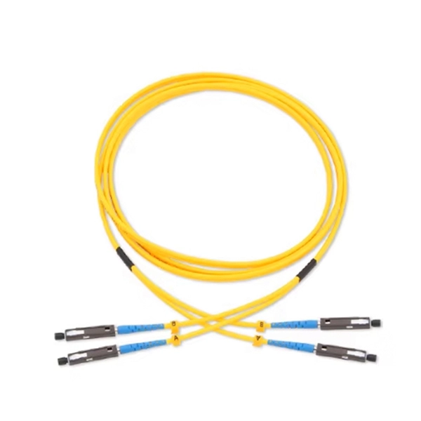
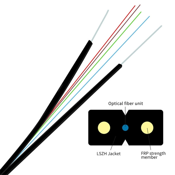
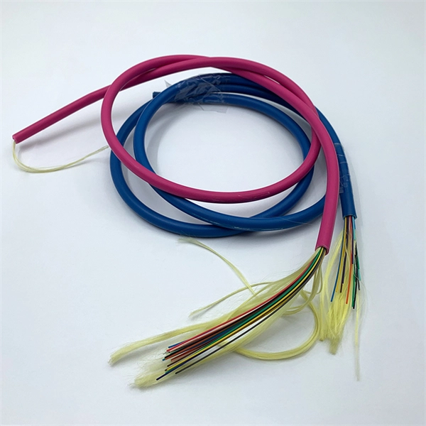
Fiber optic "cable" refers to the complete assembly of fibers, other internal parts like buffer tubes, ripcords, stiffeners, strength members all included inside an outer protective covering called the jacket. Cable provides protection for the optical fiber or fibers within it appropriate for the environment in which it is installed. You will also learn how different aspects of the product can affect budget and design. ■ The Five Key Parts of a Fiber Optic Cable A fiber optic cable. A fiber optic cable consists of five basic components: the core, the cladding, the coating, the strengthening fibers, and the cable jacket. When searching for a fiber optic cable, we need to pay attention not only to the connectors, such as SC to ST fiber cable, LC to SC fiber patch cable, or SC to. A TOSLINK optical fiber cable with a clear jacket. These cables are used mainly for digital audio connections between devices. This advanced cabling solution allows fast, secure data transfer and telecom over long distances. Understanding the components within a fiber optic cable enables. While fiber optic cable itself is cheaper than an equivalent length of copper cable, fiber optic cable connectors and the equipment needed to install them have typically been more expensive than their copper counterparts.
[PDF]

Discover the key differences between optical fiber cables and copper cables. OPTRAL analyzes the advantages and disadvantages to enhance connectivity. Optical and copper interconnection technologies represent two distinct approaches to data transmission, each with its own advantages and limitations. While fiber optics dominate in performance, copper retains its technical and economic justification. But how do you decide which one is best suited for your needs? This article delves into the technical comparison between copper and fiber optic cables. When it comes to modern data transmission, Fiber Optic cables and Copper Cables play pivotal roles in ensuring seamless connectivity. What Are Fiber Optic Cables? Fiber Optic cables function by transmitting data in the form of light pulses through optically pure glass fibers. These fibers are. “Fiber offers multiple technical advantages, including exceptional bandwidth, low attenuation and distortion over long distances, reduced bulk, as well as isolation from electromagnetic interference (EMI) and electrostatic discharge (ESD). ” Let's explore the characteristics, advantages, and. The two core material technologies used in almost all cables are fiber optic, and copper wiring. Whether you're looking at an HDMI cable, a USB cable, Ethernet patch cable, or any other kind of network of data transmission cabling, they are all built using copper or fiber optic internal wiring.
[PDF]
Abstract: Detecting partial discharges in cable joints is critical for timely defect identification and reliable transmission system operation. The electric field distribution of the optical fiber-implanted cable joint was simulated, followed by electrical performance tests, demonstrating that optical fiber implantation had a negligible effect on the electrical properties of the cable joint. A platform utilizing Mach–Zehnder–Sagnac. The results show that the average sensitivity of the sensor in the 10 kHz–80 kHz range is 71. 0 dB higher than that of the piezoelectric transducer, with a maximum signal-to-noise ratio of 65. To improve the long-term reliability and sensitivity of the sensing system, a novel method for cable joint monitoring based on implanting optical fibers. However, there is an industry gap in the literature about the highly sensitive fiber optic-based PD solution based on the acoustic emission principle. This paper aims to fill such an industry gap. In this paper, the fiber optic-based PD sensing (OptiFender) technology is applied to monitor the PD.
[PDF]
Electra is a leading supplier of cable trays and accessories in Qatar and offers multiple options in the segment, that can be customized as well. The range of cable trays and accessories from the house of El.
[PDF]
A practical, engineering-focused guide to planning and installing underground fiber optic cables with the right cable structure, trench design and protection level for long-life, low-risk networks. Match trench method with the correct underground fiber structure (GYTS . Installing fiber underground is one of the most durable ways to protect a network's backbone — when it's done right. Direct-burial fiber cable eliminates the need for continuous conduit runs and can be faster and more cost-effective on long, open runs. But because the cable sits in soil exposed to. 1. 01 This procedure provides general information for the installation of Prysmian fiber optic cables in direct buried applications. The methods described are intended for guideline use only, as it is impossible to cover all the various conditions that may arise during an installation. Individual. ion) and “ Installed” (after installation). The following formulas may be used to determine general guidelines for installing Corning Optical Communications fiber optic cable; however, refer to the cable specifi simply double the minimum working bend radius. Split cable guides and split 40-in. Fiber optic cable transmits data as pulses of light through thin strands of glass, offering superior bandwidth and distance capabilities compared to traditional copper wiring.
[PDF]
The modern world relies heavily on electrical and communication cables that must be managed and supported across vast distances in commercial and industrial settings. A cable tray is an organized support structure designed to secure and route these insulated electrical cables. In the electrical wiring of buildings, a cable tray system is used to support insulated electrical cables used for power distribution, control, and communication. Cable trays are used as an alternative to open wiring or electrical conduit systems, and are commonly used for cable management in. Whether you're planning a new office setup or upgrading your existing network, the choice of a cable tray system plays a significant role in ensuring the reliability and scalability of your structured cabling solution. It acts as a. en completely installed, without damage either to conductors or structural system use maintain spacing or to keep cables in place when the tray is ect the minimum bend ra-dius for cables as they exit the bottom of the cable tray. A rung spacing of 6 to 9 inches (150 to 230 mm) is preferable when. Explore various cable tray types and sizes for electrical installations. Learn about ladder, perforated, solid-bottom, wire mesh, and channel trays in this complete guide. What is Cable Tray Systems? 1.
[PDF]
Tray cables (TC) are multi-conductor cables designed and rated for installation in cable trays and raceways or supported by messenger wires. Cable tray may be used as the Equipment Grounding Conductor (EGC) in any installation where qualified persons will service the installed cable tray system. There is no restriction as to where the cable tray system is installed. The metal in cable trays may be used as the EGC as per the limitations. maintain spacing or to keep cables in place when the tray is ect the minimum bend ra-dius for cables as they exit the bottom of the cable tray. A rung spacing of 6 to 9 inches (150 to 230 mm) is preferable when the cable tray cont d for instrumentation and control applications that require. The most frequently used tray cables are: Type TC – Tray Cable – (NEC Article 336) –Power and control tray cable type TC is a factory assembly of two or more insulated conductors, with or without associated bare or covered grounding conductors, under a non-metallic jacket. TC cables are rated for. Hubbell Wiring Device-Kellems and Hubbell Premise Wiring are divisions of Hubbell Incorporated, a U. headquartered manufacturer with over 130 years of supplying solutions for the electrical and data markets. At the panel, the cable is installed in conduit (s) for the vertical.
[PDF]
This guideline defines the requirements and standards for design of underground electrical and telecommunication pathway systems. The guideline covers concrete encased duct banks and manholes for primary (medium voltage) power distribution cables and telecommunications. The UGS Manual provides guidance and standards pertaining to installing and working with underground structures for electrical facilities. Also included are. The purpose of this Distribution Standards manual is to provide the basis for standardized, uniform, and consistent engineering, construction and maintenance practices for the Nashville Electric Service (NES) system. The contents of this manual contain minimum requirements used in designing and. This section contains the requirements for equipment and installation (including manholes, switch vaults and pull boxes) relating to the Sub-transmission, Distribution, and Control of electric power ranging from 600-Volts to 25,000-Volts, such as substations, switchgear, circuit breakers, and. stent and reliable underground power distribution system. These standards are required to be used by anyone who is involved with design or installation of underground power distrib ion systems within the St. George City service territory. All high voltage, 600 volts or higher, underground power. FILING INSTRUCTION: This bulletin replaces RUS Bulletin 1728F-806, Specifications and Drawing for Underground Electric Distribution, dated June 2000.
[PDF]
Understand how to choose fiber optic cable by comparing single‑mode vs. multimode, network speed and distance needs, cable jackets/fire ratings, connectors, cost and future‑proofing for data and telecom networks. Written by Ben Hamlitsch, trueCABLE Technical and Product Innovation Manager RCDD, FOI There are many advantages when it comes to using fiber optic cable in your telecommunications infrastructure. Fiber optic technology offers several key benefits including higher bandwidth for data. Fiber optic internet is a form of broadband that uses a network of bundled tiny glass fibers called fiber optic cables to deliver internet service via light waves. internet service? The technical difference is that most forms of traditional internet service transfer information by sending electric. Transmitted with flashes of light through strands of glass, fiber-optic internet is the most advanced broadband technology available. Because data can travel faster across greater distances with glass than with cable, the connection speed is much faster with a 100% fiber-optic network.
[PDF]

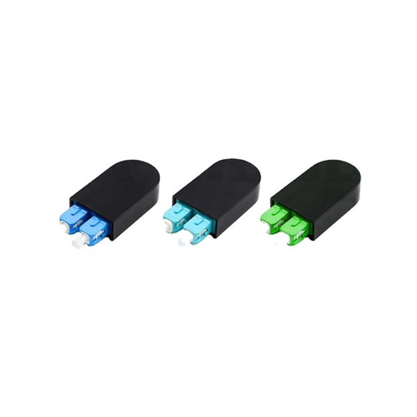
The key to choosing the appropriate one is to understand the theory on which each operates and the application that the attenuator will be applied to. Of course, you also need to be able to determine the attenuator value in decibels required for your application. Later in this article, we will discuss about the various advantages, disadvantages and application of attenuation. What is Attenuation? How Attenuation can be Prevented? What is Attenuation? Attenuation is a term in communication that refers to loss (reduction) in signal strength when a signal is. An optical attenuator, or fiber optic attenuator, is a device used to reduce the power level of an optical signal, either in free space or in an optical fiber. The basic types of optical attenuators are fixed, step-wise variable, and continuously variable. Optical attenuators are commonly used in. Fiber-optic attenuators are a specific type of optical attenuators which are used in fiber optics, e. for achieving a suitable signal level for a data receiver in a telecom system. Usually, such attenuators either have a housing equipped with some type of fiber connectors (e. The attenuator circuit will allow a known source of power to be reduced by a predetermined factor, which is usually expressed as decibels. Signal levels must be strong enough for data interpretation but not so strong as to damage the circuits in the receiver. Excessive fiber optic signal strength exceeding.
[PDF]