OPGW (Optical Ground Wire) is a kind of cable that comprises the dual functions of grounding and fiber optic communication. It is increasingly utilized in high-voltage transmission lines as a functional element that both safeguards the power system and allows data sharing. OPGW cable in transmission line systems is a unique hybrid solution that combines the functions of grounding and communication into one efficient design. It typically consists of optical fibers encased within an aluminum or steel wire, providing both strength and data transmission capabilities. Enter Optical Power Ground Wire (OPGW) cables 1 —a technology that addresses these needs in a single, integrated solution. As someone who has spent years in the optical communications industry, I've witnessed firsthand how OPGW cables have transformed the landscape of power and telecommunication. An optical ground wire (also known as an OPGW or, in the IEEE standard, an optical fiber composite overhead ground wire) is a type of cable that is used in overhead power lines. An OPGW cable contains a tubular structure with. OPGW is primarily used by the electric utility industry, placed in the secure topmost position of the transmission line where it “shields” the all-important conductors from lightning while providing a telecommunications path for internal as well as third party communications. This guide explores its design, advantages, and applications in modern energy and telecom.
[PDF]
Recommendation ITU-T L. 89 describes the general requirements and a design guide for suspension wires, telecommunication poles and guy-lines that support aerial cables for optical access networks. This Recommendation also describes loads applied to the infrastructures. Aerial infrastructure. Teleworking, online games, online medical consultations, online education - all these services are enabled by fast fi bre optic broadband networks. The intent of such a. These cables vary significantly in material, construction, and application. The core composition and number of wire strands determine their strength, flexibility, durability, and resistance to environmental factors. Understanding the different types helps in selecting the right cable for. 40. FO-VC2 JOINT USE - VERICAL MIDSPAN CLEARANCES 48. FO-GB GROUNDING AND BONDING 49. APPENDIX A - COVER SHEET / TOC 52.
[PDF]
Tray cables (TC) are multi-conductor cables designed and rated for installation in cable trays and raceways or supported by messenger wires. Cable tray may be used as the Equipment Grounding Conductor (EGC) in any installation where qualified persons will service the installed cable tray system. There is no restriction as to where the cable tray system is installed. The metal in cable trays may be used as the EGC as per the limitations. maintain spacing or to keep cables in place when the tray is ect the minimum bend ra-dius for cables as they exit the bottom of the cable tray. A rung spacing of 6 to 9 inches (150 to 230 mm) is preferable when the cable tray cont d for instrumentation and control applications that require. The most frequently used tray cables are: Type TC – Tray Cable – (NEC Article 336) –Power and control tray cable type TC is a factory assembly of two or more insulated conductors, with or without associated bare or covered grounding conductors, under a non-metallic jacket. TC cables are rated for. Hubbell Wiring Device-Kellems and Hubbell Premise Wiring are divisions of Hubbell Incorporated, a U. headquartered manufacturer with over 130 years of supplying solutions for the electrical and data markets. At the panel, the cable is installed in conduit (s) for the vertical.
[PDF]
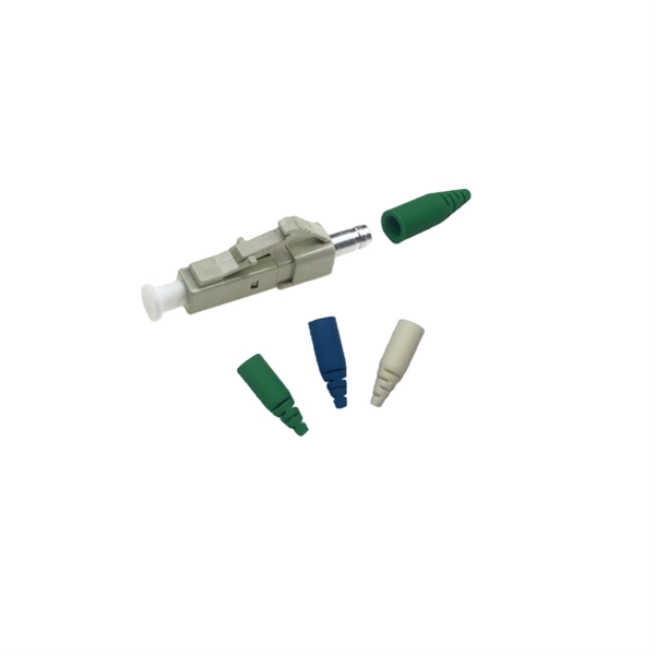
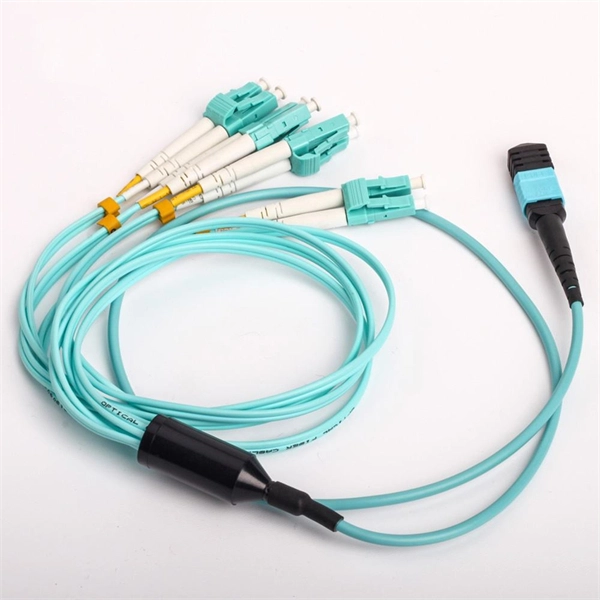
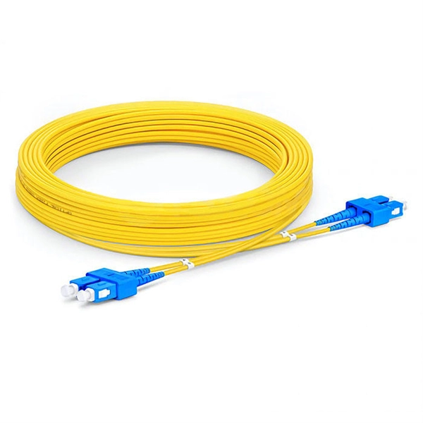
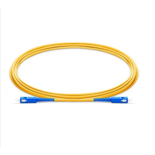
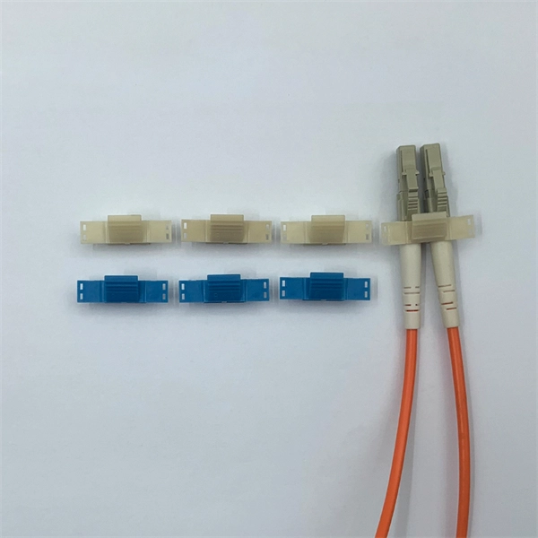
Get the wrong connector type, the wrong polish, or skip proper fusion splicing technique—and you're looking at elevated signal loss, increased back reflection, and a field termination that fails certification. Once you nail the logic chain— raw fiber → protected cable → spliced pigtail interfaces → flexible patching —you control loss budgets, installation time, and maintenance risk. Key takeaway: Treat the four items like a relay team. Each runs a specific leg so your network hits performance targets. In the intricate ecosystem of fiber optic networks, two components play a critical role in ensuring seamless connectivity: patch cords and pigtails. While both are essential for linking fibers to devices or other cables, they serve distinct purposes and are designed for specific scenarios. Executive Summary: A fiber optic pigtail is one of the most commonly specified yet least understood components in structured cabling. Despite their widespread use and numerous advantages, there are some circumstances in which they might not be the ideal option. A fiber optic pigtail is very practical for on-site terminations where fusion or mechanical splicers are used. Preterminated connectors offer several advantages over. Today, I'll show you how to pick the right patch cord or pigtail — step by step. A Fiber Patch cord connects two devices. You plug it into a switch, router, or patch panel. It's ready to use out of the box. A pigtail is for splicing.
[PDF]
This Technical Brochure describes the induction phenomena (inductive, capacitive and conductive) that can lead to presence of voltage and currents on disconnected cable systems. The optical fiber composite overhead ground wire (OPGW) has been widely used in power transmission lines. Methods of calculation to evaluate those values and touch voltages are detailed and analysed, associated with various. working on cables u al, photocopying, recording or otherwise, without the prior written or use by members of the Energy Networks Association to take account of the conditions which apply to them. Advice should. Literature review: An in-depth literature review covering the modelling and calculations of the conditions relating to faults caused by interactions between fibre optic cables and power cores in submarine cables. Examples of electrically conductive installations where induced voltage may occur could be: • Overhead lines or cables out of opera- tion •.
[PDF]
This document discusses techniques for trenching and laying optical fiber ducts. Installing fiber optic cables underground involves far more than digging trenches and placing cables. It forms a critical backbone for modern communication networks across both urban and rural environments. Project success depends on careful planning, precise installation practices, and proper. Installing underground fiber optic cables is critical to establishing high speed internet infrastructure that delivers reliable connectivity for businesses nationwide. Fiber optic cables are the shining stars of modern connectivity, transmitting data at lightning-fast speeds through glass. This comprehensive guide walks through the essential steps and best practices for successful underground fiber optic cable deployment, ensuring optimal performance and longevity of your network installation. Why Choose Underground Fiber Optic Installation? Underground fiber optic installations. Placing cables underground has the added benefits of reducing transmission losses, aiding planning consent and reduced risk of service supply loss through extreme weather.
[PDF]
Need some clarification about NEC 770. 47 (B), it says that the direct buried conductive fiber optic cable shall be 12 in (300 mm) away from the power cables. Separating high-voltage power cables from low-voltage communication cables is a fundamental requirement in any electrical installation. This practice is mandatory for two distinct reasons: ensuring the safety of the structure and its occupants, and preserving the integrity of sensitive data. Maintaining proper separation between power, data, and limited energy cabling is foundational to system performance, safety, and code compliance. Separation isn't just an EMI precaution — it protects signaling, reduces rework, and ensures pathways meet inspection expectations across risers. TECHNICAL GUIDELINE July 30, 2020 TG030 Rev. 4 Pathway Separation Between Telecommunication Cables and Power Cables Communications cables are, by design or necessity, often installed in close proximity and/or in the same pathway as power service cables. The electrical energy of the power cables can. This standard titled “Commercial Building Standard for Telecommunications Pathways and Spaces” is a joint publication of ANSI/TIA/EIA. Its current version (ANSI/TIA/EIA/-569-B) was published in October 1, 2004 and describes EMI aspects in Article 10. ca with numerous contributions by others. "UTP Separation Guidelines From EMI Sources". The values are the same as the cabling pathways standard, EIA-569, table 4.
[PDF]
Abstract: Detecting partial discharges in cable joints is critical for timely defect identification and reliable transmission system operation. The electric field distribution of the optical fiber-implanted cable joint was simulated, followed by electrical performance tests, demonstrating that optical fiber implantation had a negligible effect on the electrical properties of the cable joint. A platform utilizing Mach–Zehnder–Sagnac. The results show that the average sensitivity of the sensor in the 10 kHz–80 kHz range is 71. 0 dB higher than that of the piezoelectric transducer, with a maximum signal-to-noise ratio of 65. To improve the long-term reliability and sensitivity of the sensing system, a novel method for cable joint monitoring based on implanting optical fibers. However, there is an industry gap in the literature about the highly sensitive fiber optic-based PD solution based on the acoustic emission principle. This paper aims to fill such an industry gap. In this paper, the fiber optic-based PD sensing (OptiFender) technology is applied to monitor the PD.
[PDF]
CRU provides comprehensive, accurate and up-to-date price assessments and research reports for bare optical fibre across various key regional markets, combined with insights into the factors and events affecting markets. Market Forecast By Mode (Single Mode Fiber, Multi-Mode Fiber), By End-Use (Telecommunications, Networking, IT & Data Centers, Broadcast), By Application (Telecommunication, Power Utilities, Medical, Industrial), By Fiber Type (Glass Fiber, Plastic Fiber) And Competitive Landscape How does. Based on our observations and market communication with upstream suppliers, the single-mode fiber market in China has experienced an unprecedented price surge in the first two months of 2026. This article summarizes the latest fiber optic price data as of March 9, 2026, along with the recent. According to APO Research, The global Fiber Optic Cables market was valued at US$ million in 2023 and is anticipated to reach US$ million by 2030, witnessing a CAGR of xx% during the forecast period 2024-2030. North American market for Fiber Optic Cables is estimated to increase from $ million in. How does 6W market outlook report help businesses in making decisions? 6W monitors the market across 60+ countries Globally, publishing an annual market outlook report that analyses trends, key drivers, Size, Volume, Revenue, opportunities, and market segments.
[PDF]
In this video, we'll walk you through the process of wiring a home distribution box with a detailed connection diagram. Whether you're an electrician or a DIY enthusiast, this guide will help you understand the basics of home electrical distribution. more Welcome to our. An electrical panel box, also known as a breaker box or a distribution board, is a crucial component of any electrical system. It serves as a central hub for distributing electricity throughout a building, ensuring that power is delivered safely and efficiently to all the required locations. Follow this guide for a clear and safe connection process: Before starting, always ensure the main power is turned off to avoid electrical shock. Covers wiring, placement, standards, and expert tips for a compliant setup. It takes the incoming power and safely distributes it to different circuits throughout your building. This panel routes power from the utility service to every circuit while housing circuit breakers that provide overcurrent protection. What is Distribution Board? Distribution board.
[PDF]
This guideline defines the requirements and standards for design of underground electrical and telecommunication pathway systems. The guideline covers concrete encased duct banks and manholes for primary (medium voltage) power distribution cables and telecommunications. The UGS Manual provides guidance and standards pertaining to installing and working with underground structures for electrical facilities. Also included are. The purpose of this Distribution Standards manual is to provide the basis for standardized, uniform, and consistent engineering, construction and maintenance practices for the Nashville Electric Service (NES) system. The contents of this manual contain minimum requirements used in designing and. This section contains the requirements for equipment and installation (including manholes, switch vaults and pull boxes) relating to the Sub-transmission, Distribution, and Control of electric power ranging from 600-Volts to 25,000-Volts, such as substations, switchgear, circuit breakers, and. stent and reliable underground power distribution system. These standards are required to be used by anyone who is involved with design or installation of underground power distrib ion systems within the St. George City service territory. All high voltage, 600 volts or higher, underground power. FILING INSTRUCTION: This bulletin replaces RUS Bulletin 1728F-806, Specifications and Drawing for Underground Electric Distribution, dated June 2000.
[PDF]
Understand how to choose fiber optic cable by comparing single‑mode vs. multimode, network speed and distance needs, cable jackets/fire ratings, connectors, cost and future‑proofing for data and telecom networks. Written by Ben Hamlitsch, trueCABLE Technical and Product Innovation Manager RCDD, FOI There are many advantages when it comes to using fiber optic cable in your telecommunications infrastructure. Fiber optic technology offers several key benefits including higher bandwidth for data. Fiber optic internet is a form of broadband that uses a network of bundled tiny glass fibers called fiber optic cables to deliver internet service via light waves. internet service? The technical difference is that most forms of traditional internet service transfer information by sending electric. Transmitted with flashes of light through strands of glass, fiber-optic internet is the most advanced broadband technology available. Because data can travel faster across greater distances with glass than with cable, the connection speed is much faster with a 100% fiber-optic network.
[PDF]
Microducts are pipes used for the installation of fiber optic cables, can be produced in different colors and have high crush resistance. Available Universal Routing Kits 24F or 36F enable quick separation of fibers into 2 x 12 or 3 x 12 fiber sets with a furcation tube that protects the fibers from sharp edges in closures and cassettes. These universal routing kits provide the ultimate solution for those users who want to route. The kink-resistant buffer tube contains multiple 12-fiber sets of color-coded fibers. Each set within the buffer tube is grouped using dual color-coded binder threads. The dry-blocked core is made up of SZ-stranded buffer tubes around a central strength member. The low-friction, high-strength. Loose tube cables to install in microducts (Blowing). Available in high density of fibers. Can be directly terminated. Loose tube cables for indoor and outdoor. Loose tube cables with flexible tubes for indoor. MLT Microduct optical fiber cables are robust solutions for micro duct outside plant installations. They have stranded micro loose tubes and water blocking gel, they ensure durability and reliability. The addition of a thermoplastic dual jacket in certain models enhances resilience and ease of. Prysmian's microduct cables offer a step forward in cable miniaturization by boasting world record fibre densities and cable diameters. EasyFiber® Microduct, have a thin outer jacket for fast and easy installation.
[PDF]
Proper fiber optic termination is a crucial process for ensuring the reliability, performance, and long-term durability of any fiber optic network. The process of fiber optic cable termination is the essential act of connecting fiber optic cables to devices, patch panels, or other. Fiber optic joints or terminations - where cables are terminated - are made two ways: 1) connectors that mate two fibers to create a temporary joint and/or connect the fiber to a piece of network gear (left) or 2) splices which create a permanent joint between the two fibers (right). Thus, you will put the cable across the points, stretch it to determine length, cut it accordingly, and place the connector on each end. After that, the patch panel attaches to it. Each cable has a connector attached. A. Once fiber optic cables have been successfully placed, we can focus on managing the ends of the fibers. This process depends on the project's needs and identifying a solution that aligns with the current situation. We can make suggestions that typically benefit the current circumstances and result. Where copper twisted pairs tend to terminate with an RJ45 plug, fiber optic connectors come in all sorts of shapes and sizes, with all manner of different use cases in mind. An optical fiber connector is used to join optical fibers where a connect/disconnect capability is required.
[PDF]
A practical, engineering-focused guide to planning and installing underground fiber optic cables with the right cable structure, trench design and protection level for long-life, low-risk networks. Match trench method with the correct underground fiber structure (GYTS . Installing fiber underground is one of the most durable ways to protect a network's backbone — when it's done right. Direct-burial fiber cable eliminates the need for continuous conduit runs and can be faster and more cost-effective on long, open runs. But because the cable sits in soil exposed to. 1. 01 This procedure provides general information for the installation of Prysmian fiber optic cables in direct buried applications. The methods described are intended for guideline use only, as it is impossible to cover all the various conditions that may arise during an installation. Individual. ion) and “ Installed” (after installation). The following formulas may be used to determine general guidelines for installing Corning Optical Communications fiber optic cable; however, refer to the cable specifi simply double the minimum working bend radius. Split cable guides and split 40-in. Fiber optic cable transmits data as pulses of light through thin strands of glass, offering superior bandwidth and distance capabilities compared to traditional copper wiring.
[PDF]