In the ring distribution network, differential relays, which rely on communication between the protection relays, are used for the underground cable protection. To guarantee cable protection when communication is failed, an auxiliary protection by using directional overcurrent. This solution is based on Recommendation ITU-T G. 1344, which defines the protection switching protocol and mechanisms for Ethernet ring network topologies which will be described in detail in this document. This guide is intended for Alcatel-Lucent Enterprise's Business Partner sales and. The G. This feature uses the G. 8032 Ethernet Ring Protection (ERP) protocol version 1, defined in ITU-T G. 8032, to provide protection for Ethernet traffic in a ring topology with. Fiber rings provide resiliency to protect network services, but Spanning Tree for Ethernet rings does not provide fast failover when a link in the ring fails. In. Distance relays are applied as short-circuit protection in almost all transmission systems where overcurrent relays cannot be used for reasons of selectivity, fault detection requirements or where there is a need for improved fault clearing times. They are mainly applied in ring networks with.
[PDF]
Earth fault protection based on measured or calculated residual current values: If a breaker fails to be triggered by a tripping order, as detected by the non-extinction of the fault current, this backup protection sends a tripping order to the upstream or adjacent breakers. In electric power systems and industrial automation, ANSI Device Numbers can be used to identify equipment and devices in a system such as relays, circuit breakers, or instruments. The device numbers are enumerated in ANSI / IEEE Standard C37. 2 Standard for Electrical Power System Device Function. In North America protective relays are generally referred to by standard device numbers. ANSI IEEE Standard Device Numbers are below: (the more commonly used ones are in bold) 86T is a Lockout Relay for a. The ANSI standard device numbers ( As per ANSI/IEEE standard C37. 2) are used in the design of an electrical power system. The list of ANSI device numbers with their acronyms is as given below. Save my name, email. The protection and control devices in electrical equipment can be referred to by numbers, with appropriate suffix letters when necessary, according to the functions they perform. Even in those parts of the world where IEC standards are predominate, the use of ANSI numbering. There are two methods for indicating protection relay functions in common use. The functions are supplemented by letters where amplification of the function is required. The other is given in IEC 60617 and uses.
[PDF]
Protection is accomplished by application of a definite time overcurrent option. Current setting is greater than full load current but is lower than the motor starting current. Should a motor stall whilst running, or fail to start, due to excessive. When a motor starts, it can draw 6-8 times its full-load current for a brief period, creating significant challenges for circuit protection, voltage regulation, and system capacity planning. Understanding motor starting characteristics is essential for proper breaker sizing, motor protection relay. These time-overcurrent elements support the IEC and U. (IEEE) time-overcurrent characteristics. Electromechanical disc reset capabilities are provided for all time-overcurrent elements. protection and fault clearance in abnormal situations. The main features of the motor relay include thermal overload protection, motor start-up time supervision, locked rotor protec ion, and protection against too frequent motor starts. Addi ionally, differential protection can also be included. In order to prevent damage to the contactor, the maximum peak let-through current (Ip ) and maximum clearing energy (I2t) (amps2 seconds) of the fuse must be less than the equivalent ratings for the contactor. The clearing time and let-through characteristics of the fuse must be considered when.
[PDF]
The article provides an overview of protective relaying principles and their applications for high-voltage power system components. It covers the protection methods for generators, transformers, buses, and transmission lines using various relay types to detect and. Protective relaying is the backbone of fault detection and system isolation in As transmission systems grow increasingly complex with integration of renewables and smart technologies, the design, configuration, and application of protective relays have become more critical than ever. This article. tensify their search for reductions in capital investment and operating expenses. Faced with the continuing demand for more and more power in an environmentalist era, many operating companies are seeking, among other things, a means for supplying eliable power with fewer transmission lines and. SIPROTEC 7SD82 provides compact, cost-optimized line differential protection for medium- and high-voltage systems. It ensures safety with 3-pole tripping in 19 ms and high availability via conformal coating. The modular SIPROTEC 7SD86 is specifically designed for line differential protection of. Still deciding? Get samples first! Order sample Still deciding? Get samples first! Order sample. In HV (High Voltage) and MV (Medium Voltage) substations, relay protection safeguards critical assets such as transformers, circuit breakers, and lines. Effective relay protection depends on.
[PDF]
This connection is used to driving a Neutral Displacement Relay for detection of Earth fault in non-effectively earthed systems. Earth faults causes displacement of system neutral, particularly in the case of unea.
[PDF]
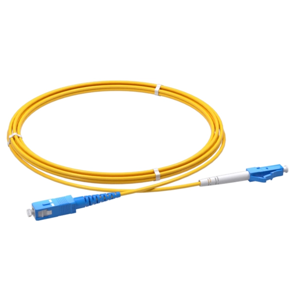
Temukan daftar Supplier, Pabrik, Importir, Distributor dan Toko Kabel Patch Cord untuk wilayah Indonesia . Update setiap hari, harga kompetitif dan layanan terpercaya. High performance and high quality connectors cable assembly are required for next generation optical networks to assure long term reliability for demanding applications such as FTTx, DWDM, 100G, CATV and etc. The connector assemblies are IEC, Telcordia and RoHS compliant. The termination passed. Prima Akses Digital Indonesia, is a Indonesian local company specialized in fiber optic product development and solution service for network infrastructure. Prima Akses Digital Indonesia, established in 2020, is supported by several partner companies and management which have been experienced in.
[PDF]
LV overhead lines are protected against overcurrents using fuses or circuit breakers. Protection of MV overhead lines is usually achieved by overcurrent relays (50; 50N; 51; 51N; 67; 67N) connected to.
[PDF]
Single Line Drawing of the LV Distribution Network with feeder pillars and distribution boxes, showing cable length, size, voltage drop, and percentage voltage drop. All orders over MVR 300 qualify for free delivery, while orders under MVR 300 are subject to a MVR 50 delivery fee. In addition, we do delivery of goods up to Jetty/boat. In cases where the goods are requested to be delivered to a vessel, details. Let us help you with your questions and queries. Send a message to Viber: 7317894 Promotions, new products and sales. Directly to your inbox. If Datasheet includes multiple models, the model number should be highlighted Datasheet of Transmission equipment. Busbar configuration, dimensions, materials and rating. Single Line. © 2024 E-Talk Maldives. Nuomak is proud to announce a new cooperation with a client in the Maldives, for whom we have manufactured PS cabinets, MCCBs, and transparent waterproof electrical distribution boxes. These products are specially designed to meet the challenges of high humidity, salt spray, and harsh coastal. Can't find the product you need? Please give us feedback Dongfeng-covering various types of distribution boxes_rich and diverse product system, covering various types of distribution boxes and cabinet products.
[PDF]
The total interruption time for a modern high-voltage SF6 circuit breaker is typically between 40 to 60 milliseconds on a 50Hz grid, or 2 to 3 cycles. This is the total time from the trip signal to the final arc extinction, a critical parameter for grid safety. While knowing the total time is a. When a SF6 circuit breaker (CB) hits its critical low pressure, its fault interrupting capability can be compromised. Most TOs protect against this by either auto-opening the CB prior to reaching the critical low-pressure level or by blocking the CB from tripping (when it reaches the critical. The protected zone is defined and limited by different things depending on the protection function. Definite time delay means that the protection operate time dose not change or depend on the fault type or the fault current magnitude. Instead of oil, air, or a vacuum, a sulfur hexafluoride circuit breaker uses sulfur hexafluoride (SF 6) gas to cool and quench the. Page 1 Content Instruction Manual circuit- breaker GL317 With spring operating mechanisms FK3- 4 Administrator First issue Compiled by Approved by 19- 11- 2012 J. Texier Imagination at work Grid Solutions 04- 2017 D1736EN/03 GE Information 1/10. Page 2 Content Instruction Manual This. A comparison of the time it takes protective devices to operate when certain levels of normal or abnormal current pass through them. LV circuit breaker ratings.
[PDF]
Use this Protection Relay Setting Calculator to calculate pickup current, time multiplier settings (TMS), operating time, coordination time interval (CTI), and plug setting multiplier (PSM) using fault current, CT ratio, and IEC 60255 curve parameters. of protective relays in terms of protecting high voltage lines. At the beginn ng of the article it is drawn up process to protect power lines. Consequently, it is shown the method of calculation for a particular power line a d performed the calculation for setting the distance protection. These calculations are critical in industrial. ve reliable and properly coordinated relay settings. Protection coordination refers to the systematic arrangement and interaction of protective devices within an electrical distribution network to ensure that faults are isolated in a controlled and orderly manner. The. With the help of these spreadsheets below, you can make your endless calculations much easier! Contact us for more information and download:.
[PDF]
Definition of Protective Relay A protective relay is an automatic device that detects abnormalities in an electrical circuit and closes its contacts. This action completes the circuit breaker's trip coil circuit, causing the breaker to trip and disconnect the faulty section from the. Eaton's protective relays provide you with unique microprocessor-based devices that eliminate unnecessary trips, mitigate arc faults, protect motors and breakers, and provide system information to help you better manage your system. Our predictive diagnostic solutions include non-destructive testing. Here, Several circuit breakers in the fault current paths from the generators to the fault location have been tripped. Note that all generators- the power sources – have been disconnected. Therefore, the whole system has gone down, even though many circuit breakers have remained closed. The relay continuously monitors electrical parameters such as current, voltage, frequency, and phase angle. When these parameters deviate from normal operating conditions or. The rectangular devices are test connection blocks, used for testing and isolation of instrument transformer circuits. : 4 The first protective relays were electromagnetic. Protective Relays - Technical Seminar Nov 2016 - Copyright: IEEE 2 Abstract: Protective relays and devices have been developed over 100 years ago to provide “lastline”of defense for the electrical systems.
[PDF]
Distance relays, also known as impedance relay, differ in principle from other forms of protection in that their performance is not governed by the magnitude of the current or voltage in the protected circuit but rather on the ratio of these two quantities.OverviewIn, a protective relay is a device designed to trip a when a is detected. The first protective relays were electromagnetic devices, relying on coils operating on moving par. Electromechanical protective relays operate by either, or. Unlike switching type electromechanical with fixed and usually ill-defined operating voltage thresholds. Electromechanical relays can be classified into several different types as follows: "Armature"-type relays have a pivoted lever supported on a hinge or knife-edge pivot, which carries a moving contact. These relays may.
[PDF]
This paper discusses some practical aspects of implementing single-pole tripping schemes in transmission-line protection. Implementation and techniques will vary in the design of protective relaying systems that i.
[PDF]
In electrical engineering, a protective relay is a relay device designed to trip a circuit breaker when a fault is detected. : 4 The first protective relays were electromagnetic devices, relying on coils operating on moving parts to provide detection of abnormal. The rectangular devices are test connection blocks, used for testing and isolation of instrument transformer circuits. Its main purpose is to safeguard electrical equipment like transformers, generators, and transmission lines from damage due to. Eaton's protective relays provide you with unique microprocessor-based devices that eliminate unnecessary trips, mitigate arc faults, protect motors and breakers, and provide system information to help you better manage your system. Our predictive diagnostic solutions include non-destructive testing. Protective Relay Definition: A protective relay is an automatic device that senses abnormal conditions in electrical circuits and triggers actions to isolate faults. Types of Protective Relays: Protective relays are categorized by their mechanism (electromagnetic, static, mechanical) and function. Combines protection, sensors, control power, and circuit breaker in a single package Typically added to a breaker close circuit to prevent accidental reclosure after a trip. Three fundamental components required for each circuit breaker. This prevents damage to equipment, reduces downtime, and safeguards.
[PDF]

Thinner cables can be utilized to connect the control switch to the relay; this saves space, weight, and cost. The same voltage and current ratings as other types of switches, such as mechanical switches, do not limit relays. This handbook covers the code of practice in protection circuitry including standard lead and device numbers, mode of connections at terminal strips, colour codes in multicore cables, dos and donts in execution. Also principles of various protective relays and schemes including special protection. A control relay is an electrically operated switch that enables current to flow through a coil that closes or opens the switch. Relays use a small current to control a larger current, making them ideal for controlling high-power devices such as motors, lights, valves, and sensors. When a relay contact is open, this will switch power ON for a circuit when the coil is activated. You'll connect a low-power control circuit to the relay's coil (terminals 85 and 86), which then flips a switch for a separate, high-power circuit running through the. Electrical protection relay has two type protecton as HT panel protection and LT panel protection. HT panel protection relay. The HT power supply is received from GO switch and distributed to the. The rectangular devices are test connection blocks, used for testing and isolation of instrument transformer circuits. : 4 The first protective relays were electromagnetic.
[PDF]