This paper proposes a mathematical model for busbars used within a high current power supply. The obtained thermal model can be used to analyse the thermal behaviour of busbars in steady-state conditions at different values of the electric current, cross-section and length. Improving surface temperature measurement of the power cable and insulated busbar using the heat insulated layer Abstract The surface temperature measurement is susceptible to the surrounding air for the cable or the insulated busbar laid in free air. Therefore, an approach for improving their. The thermal analysis takes into account the heat conduction and convection of a copper busbar system used to supply a test bench with high currents in order to check the electro-thermal behaviour of power circuit breakers during overload and short circuit conditions. This paper proposes a. Current is supplied via bus bars or wire bonding in power supply lines for power electronics devices such as inverters. Because inverters and similar devices operate with PWM carrier frequencies of several kHz, high-frequency current flows in their bus bars. Influences from the skin effect cannot.
[PDF]
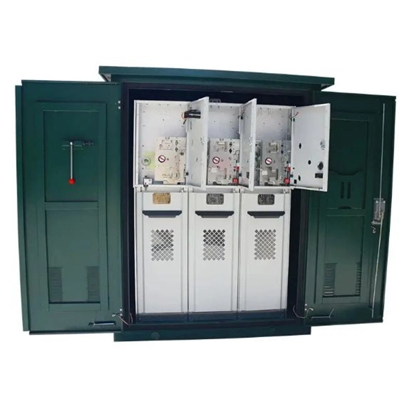
Operating at 10kV with a normal-pressure sealed structure, it uses air as the insulating medium (eliminating reliance on SF₆ gas) and features modular cabinet designs that can be flexibly combined. The AHVAC10KV10MABT is a ac-dc high voltage power supply designed for ac-dc benchtop high voltage power supplies. It converts 90 to 230V input into a high voltage output up to 10kV, with a maximum output current of 10mA. The module is designed for stable AC-DC high voltage conversion, offering. In electric power distribution, a busbar (also bus bar) is a metallic strip or bar, typically housed inside switchgear, panel boards, and busway enclosures for local high current power distribution, transmission, or switching substations. They are key components in electrical systems that can efficiently collect and distribute electricity. In this blog, I will introduce busbars in detail. Its primary role is to carry large current loads and connect multiple circuits together. When the required voltage is achieved, then rotate the potentiometer lock clockwise to High efficiency AHVAC10KV10MABT, is designed for achieving AC-DC conversion from AC voltage. The 10kV (Flexible Combination of Multiple Cabinet Types) Normal Pressure Sealed Air-Insulated Switchgear / Ring Main Unit is a versatile medium-voltage power distribution system designed to adapt to diverse operational needs.
[PDF]
Its primary role is to carry large current loads and connect multiple circuits together. Think of a bus bar as the main highway for electrical current—allowing it to flow between components with minimal resistance and voltage drop. In electric power distribution, a busbar (also bus bar) is a metallic strip or bar, typically housed inside switchgear, panel boards, and busway enclosures for local high current power distribution, transmission, or switching substations. Think. The electrical panel, often called the breaker box, functions as the central distribution point for all electricity entering a home. While circuit breakers are the visible safety components, the internal system that routes and distributes the power is built around the bus bar. It acts as a central hub, connecting multiple circuits and ensuring current flows efficiently. A busbar's main function is to conduct and distribute large electrical currents from one source to multiple circuits within an enclosure, acting as a central, high-capacity connection point. My insights show that understanding the practical function is key. As I've seen in the field, the textbook.
[PDF]
This guide offers a detailed busbar pricing guide for electrical contractors, explores what affects pricing, and provides strategies to get the best value busbar products suppliers near you —without sacrificing quality. Buying busbars isn't just about getting the lowest price. Your decision. Energy technology solutions for a wide variety of applications. From renewable energy sources to advanced power management systems, we provide the expertise, products, and. Where electric power distribution is needed, you'll find busbars. Whether you're searching for aluminum busbars, copper busbars or insulated busbars, you'll find them all and more at RS, in stock and ready to ship today. No matter how big or small the job at hand may be, making sure you have the. Busbars (bus bars) are integral to power distribution and serve numerous industries including automotive, industrial, and aerospace. Busbars are metal bars that can be composed of numerous alloys but are most commonly copper or aluminum. Typical busbar applications include switchgear, panel boards. Explore key factors affecting electrical busbar prices, market trends, and tips for smart purchasing to optimize cost and quality in power systems. In modern electrical distribution systems, busbars play a crucial role in ensuring efficient, safe, and scalable power delivery across industrial. Bus bars can be found in devices as common as household circuit breakers. Order Online or Call Us! 888-899-3509.
[PDF]
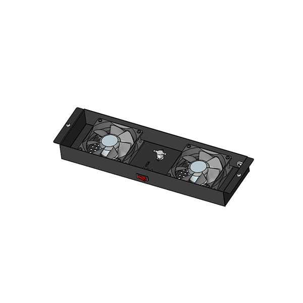
The IEC 61439 standard applies to busbar assemblies that will be installed in electrical applications with a voltage rating up to 1000 V (for AC) and 1500 V (for DC). IEC 61439 is a standard developed by the International Electrotechnical Commission (IEC) that covers design verification for low-voltage electrical products and assemblies. Generation, transmission, distribution and control of electric energy. Special service conditions, for example in ships and in rail vehicles provided that the other relevant specific requirements are complied with. Electrical equipment of. The IEC standard for busbar sizing provides detailed guidelines to help engineers select appropriate busbar dimensions. This ensures that systems operate reliably without overheating or causing electrical hazards. The new series of IEC 61439 standards were published in January 2009. This standard has brought considerable clarity in technical interpretation. It serves as a reference for the construction of. In low-voltage power distribution, the cabinet is never just a cabinet, and the busbar is never just a strip of copper. Behind every reliable low voltage switchgear lineup is a design balance that is harder than it first appears: current must flow safely, heat must be controlled, internal space.
[PDF]
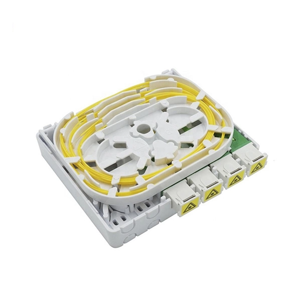
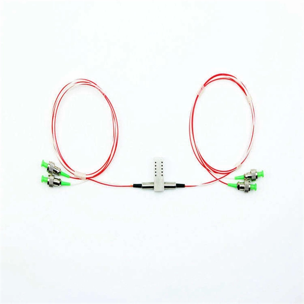
Passive media components such as cables, cable splices, and connectors cause attenuation. Although attenuation is significantly lower for optical fiber than for other media, it still occurs in both multimode and single-mode transmissions. Two fundamental mechanisms cause attenuation inside the fiber itself: absorption and scattering. These are intrinsic to the glass, meaning they exist even in a perfectly manufactured, perfectly installed fiber. Scattering is the bigger factor at the wavelengths most networks use. The silica glass. Optical attenuation is the gradual loss of flux (light intensity) as an optical signal travels through a fiber. Measured in decibels (dB), it's the logarithmic ratio of the output power to the input power. Every network has a "loss budget". F iber optic networks rely on the efficient transmission of light signals to deliver high-speed data over long distances. However, various factors can cause signal degradation, leading to performance issues and reduced network reliability. You may see slower speeds and less steady connections when signal loss goes up. Things like impurities in the fiber core and reflections at the core-cladding edge cause this drop. This can be due to a variety of factors: scattering and absorption, intrinsic. Signal attenuation in fiber optics is a key concept in telecommunications. It affects how far a signal can travel without losing.
[PDF]
EIA/TIA 568 B allows any fiber optic connector as long as it has a FOCIS (Fiber Optic Connector Intermateability Standard) document behind it. Fiber optic cold connection, also known as mechanical splicing, is a widely used method of connecting optical fibers in a network. Unlike fusion splicing, which uses heat to join two optical fibers together, cold connection uses mechanical means to create a stable and low-loss connection. Unlike fiber splicing, which is permanent, connectors allow for easy connection and disconnection of cables, making them ideal for maintenance and flexibility in. Fiber optic joints or terminations are made two ways: 1) splices which create a permanent joint between the two fibers or 2) connectors that mate two fibers to create a temporary joint and/or connect the fiber to a piece of network gear. These terminations must be of the right style, installed in a. Fiber termination refers to the process of preparing the end of a fiber optic cable to connect to another fiber, a device, or a network. Proper termination is essential for ensuring optimal performance, reducing signal loss, and maintaining the durability of the connection. Since the introduction of fiber optic technology decades ago, a variety of connector types have been.
[PDF]
There are currently three methods of looking inside a fiber optic connector: (1) Non-destructive X-ray (2) Lossless sonar (3) Destructive cross section These methods help engineers determine the causes and effects of fiber optic connector failures and monitor the connector assembly. There are currently three methods of looking inside a fiber optic connector: (1) Non-destructive X-ray (2) Lossless sonar (3) Destructive cross section These methods help engineers determine the causes and effects of fiber optic connector failures and monitor the connector assembly. Fiber Optic Center offers a unique cross-sectioning service to identify and isolate problems related to fiber optic terminations that would otherwise be invisible. All. There are two major uses for visual inspection of fiber optic connectors. Video microscopes should have ability to record images and some may have ability to analyze connector condition to standards. Look for dirt, contamination, scratches or any other problem. Since connectors are susceptible to damage that is not immediately obvious to the naked eye—the inspection phase is vital. When proceeding with the inspection of connectors, there are two main components to inspect: the connector itself and the ferrule. With the press of a single button, FOCIS Flex auto-focuses, captures and centers the end-face image, applies Pass/Fail rules, displays image and Pass/Fail results, saves results internally and/or wirelessly transfers data to a.
[PDF]
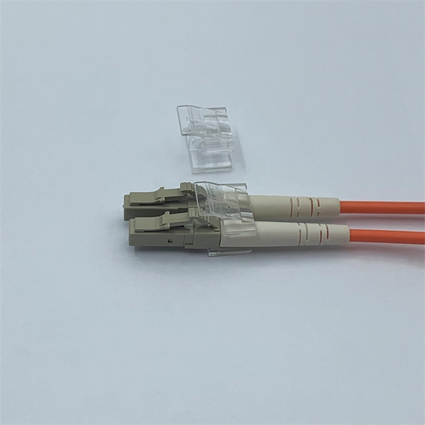
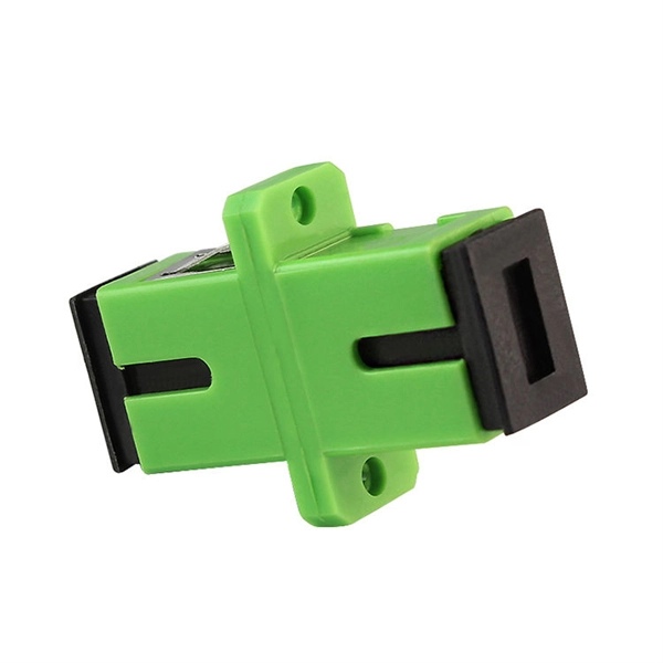
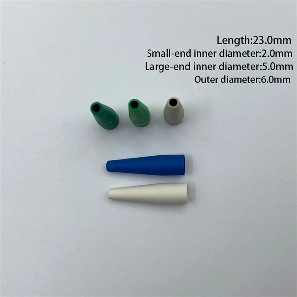
The simplest method: connect two cables pre-connectorized via a coupler (also called an adapter). The coupler aligns the two ferrules of the connectors using a zirconia sleeve. Why connect two fibers? Do you need to extend, repair, or connect two fiber optic cables? There are three methods main ones, each with its advantages and limitations. This article explains when. Optical fiber fast connectors, also known as cold connectors, are becoming increasingly popular due to their ease of use and quick installation. Unlike traditional fiber connectors that require epoxy and polishing, fast connectors use a mechanical splice to join the fibers. Another method is using a mechanical splice which involves aligning and securing the fiber ends with a precision. Fiber optic cables can be connected together using a couple of different methods: 1. This creates a permanent and low-loss connection. Connectors play a crucial role in our daily lives, yet there are some connectors that remain less familiar, such as fiber optic fast connectors. The goal is clean.
[PDF]
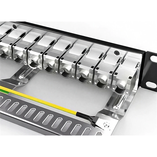
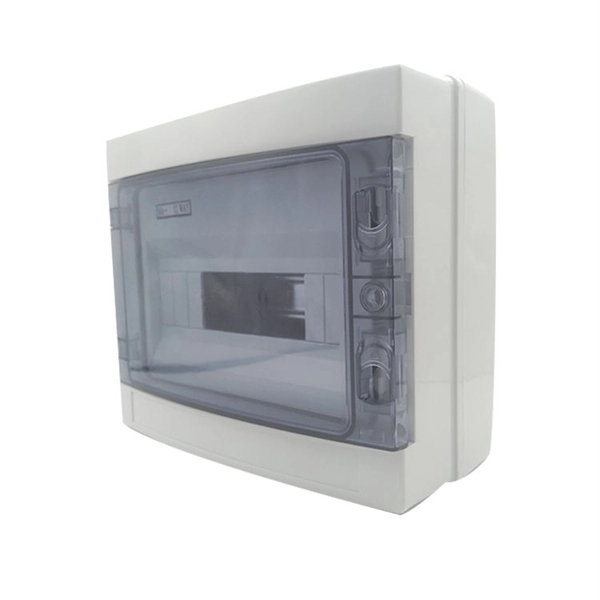
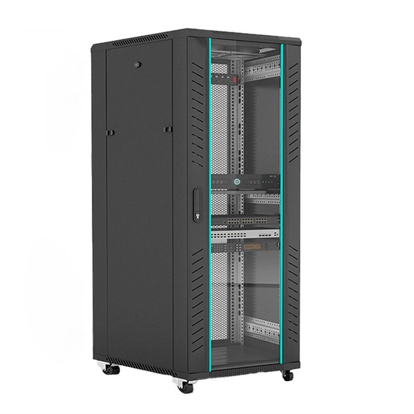
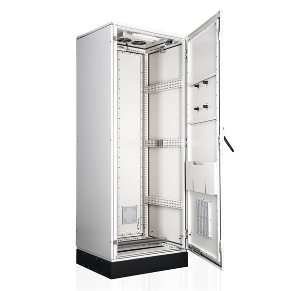
Simply put, a distribution cabinet is an enclosure that contains circuit breakers, relays, busbars, and monitoring devices. It ensures that electricity is delivered safely and efficiently to different sections of a building or facility. In electrical engineering, a power distribution cabinet refers. In this article, we explore seven essential components that play critical roles in power distribution cabinets. It acts as the main electrical pathway that distributes power from. While compliance and safety are major players in the move to busbar power, the need to optimize the use of space inside an industrial enclosure and the demand for faster, more efficient configuration and installation are also leading the charge toward busbar power. North America Copper Busbar. MCCB pan assemblies and busbars work together in distribution boxes to create a complete power distribution system. The pan assembly provides mechanical mounting and electrical connection points for circuit breakers, while busbars serve as the main conductors for power distribution, allowing. Internal components include: bus bar (bus bar), circuit breaker, conventional relay, integrated relay protection device, metering instrument, isolation knife, indicator light, grounding knife, etc. The following describes switchgear with application angle division and its power distribution related.
[PDF]
Phase A is yellow, Phase B is green, and Phase C is red DC Bus: positive red, negative blue Simulates the logo color of the busbar Voltage Unit (kV) - Color AC 0. 4 - Yellow-brown AC 3 - Dark Green AC 6 - Navy Blue AC 10 - Crimson AC 13. 8~20-Light green AC 35. The Inga–Shaba EHVDC Intertie (officially: The Inga–Shaba Extra High Voltage D. The following color codes apply to different AC and DC power systems: In some wiring systems, one phase has a higher voltage than the others, known as the high-leg. This. A 1,700 km power transmission link that transmits power from Inga Falls on the Congo River to the copper mining district of Katanga in the Democratic Republic of Congo (DRC). The Inga-Kolwezi link (formerly the Inga-Shaba link) was initially a ± 500 kV, 560 MW HVDC power transmission system. Image. Electrical wiring color codes are standardized systems used globally to identify the function and voltage of different wires in electrical installations, ensuring safety and efficiency in electrical work. These codes vary by region and application, with the National Electrical Code (NEC) and.
[PDF]
Welcome to NEP Factory, your premier destination for high-quality BusBar Trunking systems. We specialize in manufacturing of cutting-edge Busway solutions that provide exceptional power distribution for various commercial and industrial applications. Market Forecast by Countries (Saudi Arabia, UAE, Kuwait, Qatar, Bahrain, Oman, Turkey and Rest of Middle East), By Type (Low Power Busbar Systems, Medium Power Busbar Systems, High Power Busbar Systems, Plug-in Busbar Trunking, Lighting Busbar Systems), By Conductor Material (Copper & Aluminum. Multiplast (a division of FJ Group) in partnership with the Powerduct, specializes in Busbar Trunking System and provides cutting-edge solution for efficient and reliable electrical power distribution in commercial, industrial, and large-scale facilities. Designed for flexibility, Powerduct offers. Catalogue: Busbar, Cable Tray, Trolley Busbar and more! You can easily download all of the EAE catalogues on eaeelectric. As per Market Research Future analysis, the Busbar Trunking System Market Size was estimated at 6. 6 USD Billion in 2024. 17 USD Billion by 2035, exhibiting a compound annual growth rate (CAGR) of 5. Why Choose Busway?u000bBusway has emerged as a.
[PDF]
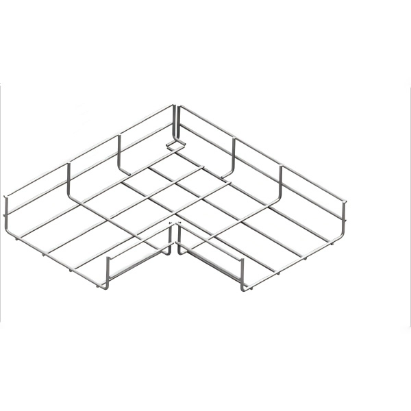
In this Shorts video, watch a step-by-step demo of installing riser bus bars and terminating MW cable joints for industrial electrical systems. Learn pro techniques for secure, durable connections and flawless finishing. Perfect for electricians, engineers, and electrical. Busbars are the unsung heroes of electrical panels, ensuring reliable power distribution and minimizing clutter. If you've ever wondered how to achieve a flawless busbar installation, you're in the right place. This guide will walk you through every step of the process, from selecting the right. These guidelines govern the busbar processing and installation procedures for all low-voltage switchgear and power distribution enclosures manufactured by our facility. The principles outlined herein encompass a comprehensive range of busbar fabrication techniques, including but not limited to. NOTE: Repeat the above operations each time a switchboard cubicle is placed. For standard torque values, refer to Standard Tightening Torques and comply with the specified torque values. Currently, Thor is the Technical Department Manager at Weisho Electric Co. Every step is crucial when installing high and low voltage. Learn how to install TE Connectivity's Raychem high voltage busbar insulation tape (HVBT). It is a heat-shrinkable, adhesive-coated tape which provides insulation enhancement and protection against accidentally induced flashover. Video is not currently available for playback.
[PDF]
Join me in this concise video as I demonstrate the meticulous process of connecting stranded wires in a junction box through soldering. Whether you're a DIY enthusiast or a professional electrician, this brief tutorial offers valuable insights into using soldering for. I was changing a switch in my house when I found a number of connections in the electrical box that were soldered rather than secured with a wire nut. The solder joints look very well done, the conductors were twisted together nicely and the solder itself was nicely done. It was not some oxidized. I have found several soldered wires inside junction boxes in my older lake house. I see mostly neutrals this way with the hots going to outlets or switches where they are looped onto the screws. If I am upgrading the junction box to a larger one I just cut the. I don't know why anyone would do this now a days but thats the interesting thing about being an inspector. I inspected a house today that someone is wiring the old school way. The grounds he used wire nuts on. more Join me. Because of different characteristics of dissimilar metals, devices such as pressure terminal or pressure splicing connectors and soldering lugs shall be identified for the material of the conductor and shall be properly installed and used. No wiring systems of any.
[PDF]