Positive busbars, which collect all positive connections. Key Steps: When wiring a pair of 12V busbars, connect the positive terminal of each load to a stud on the positive busbar and their negative terminal to a stud on the negative busbar. 5' above batteries on inside of cockpit combing below decks. Install one new positive bus bar beside the negative one separated by about two inches 3. Positive and negative busbars are physically identical apart from the red/black colours used by some manufacturers to visually differentiate between. A Complete Guide to Battery Terminal Connector Types The store will not work correctly in the case when cookies are disabled. JavaScript seems to be disabled in your browser. For the best experience on our site, be sure to turn on Javascript in your browser. Skip to Content Blog Sign In Create an. This image illustrates a standard car battery with top post terminals and labeled connectors for the positive (+) and negative (–) ends, emphasizing safe and correct installation. A battery terminal connector is a fitting or clamp that attaches to a battery's terminal to connect a cable. In other. Both positive and negative terminals are the soul of the electrical system of the car, allowing the engine to start while keeping other components running. The catch? Mix-up or loose connection can cause electrical failure, drained batteries, and damage to wiring. This blog guides you how the two.
[PDF]
Learn how to set up, calibrate, and use the FS-V11, a versatile sensor with automatic and manual calibration options, plus expansion unit compatibility. It's designed to work with various fiber optic cables and can be easily set up and calibrated with a range of options for sensitivity. Digital Optical Fiber Amplifier Sensor FV-V11 Photoelectric Sensor NPN NO or NC (Selectable via Button), 12 to 24V DC Supply Voltage, Red LED, FINE (250 µs), TURBO (500 µs), and SUPER TURBO (1 ms) Response Time, LIGHT-ON/DARK-ON (switch-selectable) Operation Modes, Digital LED monitor with seven. PNP open-collector 100 mA max. ), Residual voltage: 1 V max. Incandescent lamp: 10,000 lux max. *1 If more than one unit is used together, the ambient temperature varies with the conditions below. Mount the units on the DIN rail with mounting brackets and. Owner's manuals and user's guides for Sensors Keyence FS-V11 (P). Keyence FS-V11 (P) user manuals PDF. Browse online or download Sensors Keyence FS-V11 (P) User Manual. The orange LED is normally part of the bar graph LED monitor. It is used as a calibration indicator during the setting of the sensitivity. To connect several units, be sure to mount. Since 1996, the FS-V Series has utilised a parallel processing chip rather than a general-purpose CPU. This chip is designed especially for fi breoptic sensors in order to offer accelerated data processing and specialisation.
[PDF]
This comprehensive guide breaks down the internal structure, core components (TOSA, ROSA, lasers), and operational mechanisms of SFP optical modules, enriched with technical insights and real-world applications. The Transmitter Optical Sub Assembly (TOSA) is responsible for the emission of light. Its primary function entails converting electrical signals into optical signals. This assembly comprises a light source, such as a laser diode or a semiconductor light-emitting diode (LED), an optical interface, a. An optical module is a typically hot-pluggable optical transceiver used in high-bandwidth data communications applications. Optical modules typically have an electrical interface on the side that connects to the inside of the system and an optical interface on the side that connects to the outside. As an essential component of optical fiber communication, optical modules are optoelectronic devices that facilitate the conversion between optical and electrical signals during the transmission process. Operating at the physical layer of the OSI model, optical modules are core devices in optical. In the era of 5G, AI, and high-speed data centers, optical modules serve as the core bridge for converting electrical signals to optical signals (and vice versa), enabling fast, reliable data transmission across networks. As the core optoelectronic devices operating at the Physical Layer of the OSI model, their.
[PDF]
In the ring distribution network, differential relays, which rely on communication between the protection relays, are used for the underground cable protection. To guarantee cable protection when communication is failed, an auxiliary protection by using directional overcurrent. The use of ring circuits in 6 – 35 kV distributed electrical networks can improve the reliability of power supply. An increase in the load power and the share of distributed generation and renewable energy sources causes the redistribution of the power flow during the operation of an electrical. The selected protection principle affects the operating speed of the protection, which has a significant im-pact on the harm caused by short circuits. The faster the protection operates, the smaller the resulting ha-zards, damage and the thermal stress will be. Further, the duration of the voltage. ABSTRACT: Over current protection is the simplest form of power system protection of distribution line. In. The purpose of this study is to investigate the coordination of overcurrent relay in different types of the distribution network, which are radial, ring, and interconnected distribution system during line to ground fault occurrence at the bus. Usually, this refers to medium-voltage networks, since they are protected by numerical relay devices, as opposed to low-voltage networks, where utility operators allocate.
[PDF]
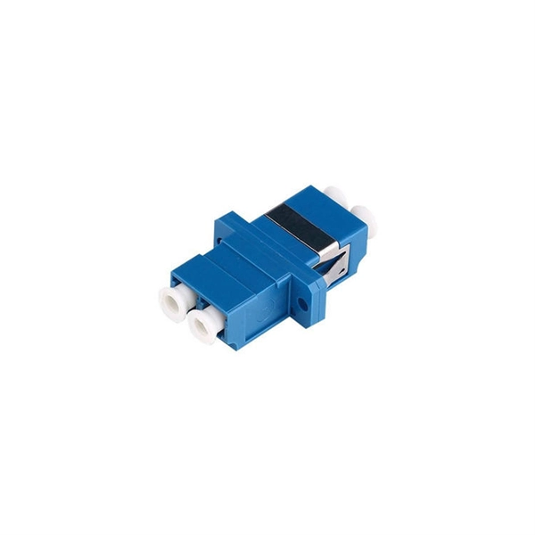
Most modern fiber-enabled network switches require an SFP transceiver module featuring a duplex (two strand) multimode OM3 or duplex single mode OS2 connection with LC connectors. Direct attach cables with pre-terminated SFP connections may also be used. Download. CONFIGURING THE SWITCH IN DESIGO CC/CERBERUS DMS. CYBERSECURITY DISCLAIMER. 44. This tutorial will explain the steps required to configure fiber optics on a Cisco switch and ensure proper connectivity in your network. Contains package contents and instructions for unpacking, setting up and adjusting the optical power of your FOS unit. Contains operating specifications and pinout information. You can access documentation for Ocean Optics. Upgrades Occasionally, you may find that you need Ocean Optics to make a change or an upgrade to your system. To facilitate these changes, you must first contact Customer Support and obtain a Return Merchandise Authorization (RMA) number. Page 8 About This Manual 000-10000-040-02-0505. Chapter 1. This document describes how to troubleshoot fiber optic interfaces by addressing some of the fiber optic module and cabling specifications. The information in this document is based on all Catalyst 9000 Series switches. This includes Doppler. Fiber optic cabling is increasingly used to connect network switches and other datacom equipment, especially in long-distance and mission-critical applications. Fiber provides: Increased internet signal bandwidth.
[PDF]
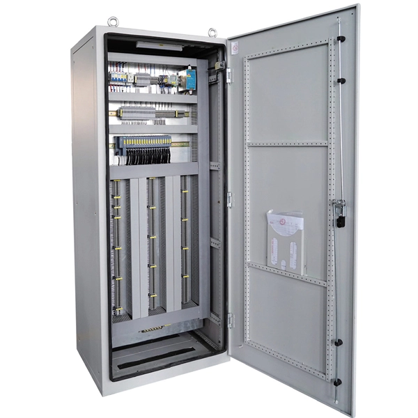
Find competitive prices for Busbar Trunking Systems at Shanghai Qiongkai Industry Co. Connect with reliable manufacturers and suppliers to meet your project needs today!. Buy Busbar Trunking Manufacturers China Direct From Busbar Trunking Manufacturers Factories at Alibaba. Help Global Buyers Source China Easily. Consider factors like conductivity, weight, and corrosion resistance. Use a material guide to select the top choices suited for your applications. Consult with. Finding a balance between quality and cost for your Busbar Trunking Systems is essential. Each product undergoes rigorous testing to ensure durability and efficiency for electrical. Scroll down to check an exclusive list of top China wholesale busbar trunking system suppliers, manufacturers (OEM, ODM & OBM), wholesalers, factory lists, distributors, exporters, importers, etc. Import busbar trunking system from various high-quality China wholesale busbar. Zhejiang Rutong Electric Technology Co. offers an OEM Bus Trunking System designed for efficient power distribution in large buildings and industrial environments.
[PDF]