This video shows 2D wave simulations of optical fibers and presents differences between single-mode and multi-mode light propagation. more Audio tracks for some languages were automatically generated. Learn more. This applet is called FIMOC (fiber-optic mode online calculator). With it you will be able to calculate and visualize the propagating modes of any step-index fiber of your choice. If you want to go directly to the software, scroll to the bottom, but if you are interested in where these modes come. Optical fiber sensors have attracted significant interest in the sensing field. This paper presents a C-shaped optical fiber sensor sensitivity enhancement through design. RP Fiber Power is a powerful software for simulation, design and optimization of fiber devices — in particular, fiber amplifiers and lasers as well as other types of waveguide lasers (and even many bulk lasers), but also fiber couplers, multi-core fibers, helical core fibers, tapered fibers and. In this proposed workflow, we couple Ansys Mechanical TM with Ansys Lumerical TM, creating an innovative workflow that can detect the position of a random mechanical strain along an optical fiber. In this proposed workflow, DFOS utilizes standard single mode optical fiber as a sensing element. 1Department of Mechanical and Aerospace Engineering, University of Texas at Arlington, 500 W.
[PDF]
In fiber-optic communications, wavelength-division multiplexing (WDM) is a technology which multiplexes a number of optical carrier signals onto a single optical fiber by using different wavelengths (i.e., colors) of laser light. This technique enables bidirectional communications over a single strand of fiber (also called wavelength-division duplexing) as well as multiplication of capacity. The. SystemsA WDM system uses a at the to join the several signals together and a at the to split them apart. With the right type of fiber, it is possible to have a device that does both s. Originally, the term coarse wavelength-division multiplexing (CWDM) was fairly generic and described a number of different channel configurations. In general, the choice of channel spacings and frequency in these co.
[PDF]
Welcome to our light sources category, where we offer advanced calibration solutions designed for precision and accuracy in scientific measurements. Our selection encompasses two primary subcategories: “Wavelength Calibration” and “Radiometric Calibration,” featuring state-of-the-art products. This. As a result of a 2-year research project, finalised in 2020, GL Optic developed new calibration facilities and created Calibration and Research Laboratory of Optical Radiation ( CARLO ). Today, CARLO is the only laboratory in Central and Eastern Europe equipped with the Black Body Radiator – the. We offer two types of light sources for calibration: Pen-Ray line sources for the wavelength calibration of spectroscopic instruments and calibrated irradiance sources covering UV-NIR. All Avantes spectrometers are factory wavelength calibrated and do not require recalibration as they have fixed slits and optics. Options include mercury-argon (253-1700 nm), krypton (427-893 nm), neon (540-754 nm), argon (696-1704 nm) and xenon (916-1984 nm) gas-discharge emission sources. Multiple LED sources can be efficiently combined into a single output beam, and offer major advantages such as long life-time, easily tunable spectrum, high power stability, and ultra-fast switching (on the microseconds level) without using moving mechanical components. Multi-Wavelength Collimated.
[PDF]
Check the electrical load and ensure that the sensors do not exceed the 10 Amp maximum. Check each wire for damage that may lead to a short. Check the following: Check if all cable connections are tightened with a torque moment of 14Nm (17Nm for the M10 model). Check if the surface area. Channel has NO voltage and there is an active fault. Check for tripped or missing circuit breaker Sticky fault on the channel. Sticky Fault - an indicator that a fault has occurred that will stay until the indicator has been cleared manually. Channel has NO. Each powernet distribution box (PNDB) on the vehicle provides up to 4 low amperage circuits (30 amp and less), and up to three high amperage circuits through midi fuses. The fuses are located behind a cover on the face of the PNDB. On vehicles equipped with a cab load disconnect switch (CLDS), the. I have the following issues, green light on shunt all red lights on distributor, no SOC on screen. Everything else is working great. In troubleshooting I removed all the fuses from the distributor just to see if the fuse lights would not illuminate red and get green power. Any. Show the control box indicator lights. Show the accessory response (or lack of response). For LED Light Kit issues, also provide a photo of the LED Y-cable (to confirm which version you have). Videos and photos are required to file warranty claims with the manufacturer.
[PDF]
Singlemode fiber features a small core diameter of just 9 µm and allows only one mode of light to propagate. This design minimizes signal loss and supports high-bandwidth applications over long distances. 5 µm) with multiple light. Single-mode fibers (also called monomode fibers) are optical fibers which are designed such that they support only a single propagation mode (LP 01) per polarization direction for a given wavelength. Higher-order modes like LP 11, LP 20 etc. It allows just one light signal – typically lasers – to pass through at a time. This keeps the signal tight and strong, making it ideal for long. Optical Fiber comes in two main categories: singlemode and multimode. Singlemode fiber is designed for long-distance data transmission, typically over distances greater than 10 kilometers. Glass or plastic are often used to make these fibers. Metal wires are used in optical fibers because they protect against damage and are immune to electromagnetic interference. This characteristic allows for significantly less signal degradation and higher data rates over.
[PDF]
When the LOS light turns red or blinks red, it usually means your ONT or fiber router is not receiving the optical signal properly from the network. In most cases, this is not just a normal WiFi issue. It usually points to a signal-side or line-side problem rather than a small. The LOS light on your router indicates the status of your internet connection to the Internet Service Provider (ISP). When it's green and steady, everything is fine. Fortunately, diagnosing and resolving these issues doesn't have to be complicated. In this comprehensive guide, we will walk you. Whether your modem is blinking orange, your router has a solid red light, or you are staring at a mysterious "DS" indicator, you will find the answer below. A solid green or white light on your modem or router almost always means everything is working normally. You might feel like you're staring into the abyss of digital darkness, wondering what went wrong. Before you panic or call tech support, there are several simple fixes you can try at home that often solve this problem in minutes. Existing Krishii Fiber customers can share their registered mobile number, area and a.
[PDF]
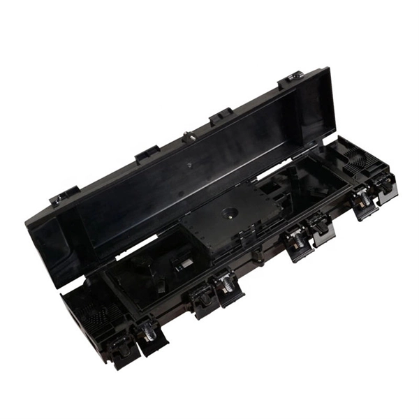
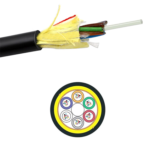
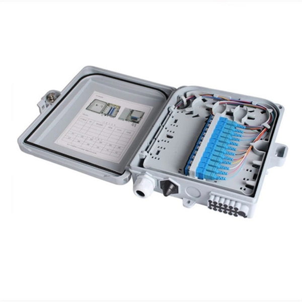
Through the adapter in the distribution box, the optical signal is led out by the optical jumper to realize the optical wiring function. An optical cable consists of three primary parts: the core, the cladding, and the protective sheath. The core is at the center of the optical cable and serves as the pathway for transmitting light signals. Surrounding the core is the cladding, which has a lower refractive index than the core. In the complex architecture of fiber optic networks, the Optical Distribution Frame (ODF) serves as the linchpin for organizing, protecting, and distributing optical signals. Whether in data centers, telecom central offices, or enterprise network rooms, ODFs enable efficient fiber management. The optical fiber distribution box is to protect the connection point where the optical cable is connected to the user end, so that the optical cable access point is stable, dustproof and waterproof. What is a fiber distribution box? 2. The. A fiber distribution box (FDB) functions as a central hub in fiber optic networks where the main cable is split into multiple individual fibers for distribution to end users. These boxes protect sensitive fiber connections from environmental factors while providing an organized framework for.
[PDF]
This report presents a comprehensive overview of the Eastern European optical fibre cables market, the effect of recent high-impact world events on it, and a forecast for the market development in the medium term. The Europe Wire and Cable Market is Segmented by Cable Type (Low-Voltage Energy Cables, Medium-Voltage Cables, and More), Voltage Rating (≤1 KV, 1–35 KV, and More), Installation Type (Overhead, Underground, and Submarine), Conductor Material (Copper, Aluminium, and Aluminium-Alloy), End-User. For the third year in a row, the East European optical fiber and bundle market recorded decline in sales value, which decreased by X% to $X in 2024. In general, consumption showed a slight setback. The report provides a strategic analysis of the optical fibre cables market in. Eastern Europe is undergoing a strategic energy transformation, driven by the expansion of solar farms, wind parks, and decentralized energy systems.
[PDF]
Wavefront shaping enables precise control of light propagation through multimode fibers, facilitating diffraction-limited focusing for applications such as high-resolution single-fiber imaging and high-power fiber amplifiers. While the theoretical intensity enhancement at the focal point is. Light from a high-power laser diode is coupled into a multi-mode fiber (diam:100 um, NA = 0. A de-speckle unit can be turned on and off to reduce any speckles that appear after light leaving the multi-mode fiber. A collimating lens (CL) after the fiber collimates the light to a certain. We present laboratory measurements demonstrating how the output beam profile from multimode fiber can be affected by the beam entry angle. In some applications, an alternative beam distribution such as a top hat or donut is desired instead of the inherent Gaussian distribution provided by typical. Light transport in a highly multimode fiber exhibits complex behavior in space, time, frequency, and polarization, especially in the presence of mode coupling. The newly developed techniques of spatial wavefront shaping turn out to be highly suitable to harness such enormous complexity: a spatial. What are the conditions for efficiently launching light into a multimode fiber? What happens to the intensity profile of light during propagation in a multimode fiber? How do bending and other disturbances affect the output beam profile? What are the challenges of maintaining single-mode.
[PDF]
Long-pass dichroic beam splitters are designed to transmit longer wavelengths of light and reflect shorter wavelengths, while short-pass dichroic beam splitters do the opposite. While this type of beam splitter is less common, it can be useful for fluorescent applications, such as. A beam splitter or beamsplitter is an optical device that splits a beam of light into a transmitted and a reflected beam. It is a crucial part of many optical experimental and measurement systems, such as interferometers, also finding widespread application in fibre optic telecommunications. In its. Beamsplitters are optical components used to split incident light at a designated ratio into two separate beams. Additionally, beamsplitters can be used in reverse to combine two different beams into a single one. Newport offers a wide variety of Beamsplitters in various shapes. a laser beam) into two (or sometimes more) beams, which may or may not have the same optical power (radiant flux). These plates are typically made of high-quality glass coated with a thin, anti-reflective film. The coating helps to minimize issues with annoying back reflections, such.
[PDF]
Resolving these issues involves steps like checking cable connections, soft resets, updating firmware, and specific solutions for different router brands like ASUS and Spectrum. It often indicates that something is wrong with your internet connection or the device itself. Fortunately, diagnosing and resolving these issues doesn't have to be complicated. In this comprehensive guide, we will walk you through the common causes of a red light on your router and provide. A router showing a red light can mean different things, like a service outage, misconfiguration, or loose connection, all of which can lead to a broken internet connection. Fortunately, there are heaps of ways to fix a red blinking light on your router. One of the first things you should try is to. Turn off the router and disconnect the power cord. Check that the PON cable is free from damage or sprains. Even if you have the best router, you may experience a loss of connection or other issues and see that dreaded red light. When it's green and steady, everything is fine. However, when it blinks red or stays solid red, it signifies a Loss of Signal, a problem preventing your router from communicating.
[PDF]