Two major factors should be considered: (1) the number of bits required to produce a statistically meaningful BER/BLER result, and (2) the baseband functionality required to verify coded BER/BLER. Bit Error Rate (BER) testing is a crucial aspect of evaluating the performance of digital communication systems. It involves measuring the rate at which errors occur in a transmitted bitstream compared to the expected bitstream at the receiver end. The BER measurement helps in assessing the quality. In digital transmission, the number of bit errors is the number of received bits of a data stream over a communication channel that have been altered due to noise, interference, distortion or bit synchronization errors. Adhering to strong layout practices ensures that the bit error rate is a random process rather than an indicator of design issues. The Bit Error Rate Analysis app is designed for analyzing BERs.
[PDF]
With the bandwidth and performance demands on Ethernet networks increasing daily, BERT has become essential for quantifying bit error rate in optical fiber communication channels and establishing confid.
[PDF]
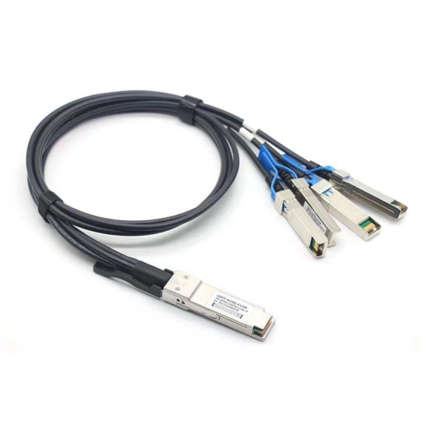
It performs error detection and alarm monitoring, serving as an essential tool for bit error testing in R&D and production of optical modules/ devices. Bit Error Ratio Tester is an instrument used to test and analyze bit error ratio in digital transmission systems, fiber optic communication systems, and digital microwave communication systems. Dimension Technology's BERT800 bit error tester series offers a comprehensive solution for testing and verifying high-speed optical transceiver modules. OPTELLENT is a provider of broadband test and measurement solutions for communications. The Company's test & measurement solutions are used in product development, manufacturing. As transmission rates continue to accelerate, accurately measuring bit error rates in optical modules is crucial to ensure reliable performance. There are three interchangeable slot boards which include QSFP, SFP+ and SFP ports separately. QSFP, SFP+ and SFP ports follow QSFP MSA, SFP+ MSA and SFP MSA. The user interface allows you to individually monitor bit error rate, error count and timer by connecting to PC via USB cable. In high-speed digital communication systems, even the smallest bit-level error can compromise performance, reduce efficiency, or lead to costly rework.
[PDF]
In practice, the bit error rate of a system for optical data transmission (e. a fiber-optic link) can be increased by noise influences (particularly in the receiver, but also in the transmitter and in amplifiers), by optical losses, and chromatic and other types of dispersion. Bit Error Rate (BER) is a critical performance metric in optical communications that measures the number of errors occurring in a transmitted data stream over a certain period. It is defined as the ratio of the number of bits received in error to the total number of bits transmitted. It quantifies the frequency of channel errors, which are often caused by interference such. Unlock AI-driven, actionable R&D insights for your next breakthrough. As optical links are increasingly used for high-speed data. A high Bit Error Rate (BER) in 800G optical modules is a multifaceted and complex issue that requires a systematic approach for step-by-step troubleshooting. It is recommended to follow an order from simple to complex to efficiently locate and resolve the problem. Use the command line interface. ted for improvement of BER in fiber optic communications. The developed scheme has been tested on optical fiber systems operating with a non-return-t -zero (NRZ) format at transmission rates of up to 10Gbps.
[PDF]
The BERT800 series bit error tester employs a modular design, featuring a control board and interchangeable interface boards. This flexible architecture allows for testing a wide range of optical transceiver modules with different packages, including OSFP, QSFP-DD, and QSFP28. Bit Error Rate (BER) is an important factor in the performance of any data transfer channel, whether wired or wireless. It can be affected by a variety of factors, including signal to noise, distortion, and jitter, so accurate BER measurement helps to pinpoint problems. We offer a full range of. The global bit error rate tester (BERT) market is expanding significantly, driven by escalating demands for high-speed data transmission validation. Current estimates place the market at approximately $XX billion in 2024, with a projected CAGR of 8. The bit error rate (BER) represents the ratio of incorrectly received bits to the total number of transmitted bits over a. A bit error rate test (BERT) typically requires a test pattern generator and a receiver set to the same pattern. They can be used in pairs, with one at either end of a link, or singularly at one end with a loopback at the remote end. Versatile 10G multiservice test modules for lab and field. As transmission rates continue to accelerate, accurately measuring bit error rates in optical modules is crucial to ensure reliable performance.
[PDF]
Provides accurate and cost-effective testing methods for the optoelectronic signal testingand anomaly simulation of high-speed optical transceiver modules. The OptoBERT™ OPB04X10 is the industry's most compact, cost-effective, easy-to-use 4-channel 10Gbps electrical bit-error-ratio tester (BERT). PBT3058 is a high-performance Bit Error Ratio Tester which can be used for physical layer characterization and consistency test of high-speed serial signal. 6TBASE/CEI-224G standards and also supports PCIe rate testing ranges through extended rate. Transmitter net measurement:. Our portable and stationary provers ensure accuracy and industry compliance for flow meters on a variety of in the field applications. Available in custom configurations and max flow rates, each prover is designed to eliminate the many prover problems of the past including our Unidirectional. In high-speed digital communication systems, even the smallest bit-level error can compromise performance, reduce efficiency, or lead to costly rework. That's why Physical Layer Tech offers precision-engineered Bit Error Rate Testers (BERTs) designed to verify data transmission accuracy and ensure. Whether you are looking for the smallest handheld 100G bit error rate tester in the world for your field job, or perhaps your needs take you into the lab, VIAVI has you covered with our accurate and easy-to-use BERT equipment for any use case. · Use control board and replaceable.
[PDF]
An OTDR is a powerful tool that helps technicians and engineers assess the health of fiber optic cables. OTDRs inject high-powered light pulses into the fiber using specialized laser diodes. As these light pul.
[PDF]
In this article, you will learn the step-by-step process of testing your solar panels using a multimeter. We will cover the essential tools you need, the specific measurements to take, and how to interpret the results. By the end of this guide, you will be equipped with the knowledge to diagnose. Solar panels are usually tested under standard conditions using a light source that mimics the light from the sun on a clear day. You can use the following method if you want to test your solar panel under standard conditions. Testing solar panels is easy with a multimeter! To test the current. Your multimeter is your best friend when testing solar panels. You can use it to check: Here's how: Multimeter — I recommend getting one that is auto-ranging. Also, a simple voltmeter won't work here. You need a multimeter that can measure both volts and amps. Locate the open circuit voltage. Learning to test a solar panel with a multimeter is an investment in your knowledge and ability to manage your own solar energy system or provide valuable services in the growing solar industry. Measure Voc (open circuit voltage) — if it reads 0V, the panel or wiring is dead. If it reads 60–80 % of rated, a bypass diode has failed. Perfect for DIY solar builders, RV owners, o. more Audio tracks for some languages.
[PDF]
To check a fiber connection, connect a jumper to the optical source port and the other end to an optical meter. Press the “test” or “signal” button to send a signal from the source to the meter. In this blog, we'll explore different methods, including using a flashlight, advanced tools like Fluke testers, and more cost-effective options for testing fiber optics. First, we'll show you the. This guide will walk you through diagnosing and resolving common fiber network issues efficiently. Why Do Fiber Networks Fail? Despite their robustness, fiber networks can fail due to: Physical Damage : Cuts, bends, or contamination in fiber cables or connectors. Below is an in-depth guide on how to assess the health and performance of a fiber optic connection: Before relying on technical tools, start. While there are many different fiber optic cable tests, the most common version is an insertion loss test, also known as an attenuation, jumper, or connectivity test. This test requires a special testing kit and protective eyewear, but it will help you diagnose problems with the cable's. We'll explain why it's vital to test fiber optic cables, the three most popular methods, and when you should use them. Related: Fiber Optic Connectors – Identification Guide Regularly testing fiber optic cables helps minimize network downtime, lengthens the network's longevity, reduces maintenance.
[PDF]
Check the electrical load and ensure that the sensors do not exceed the 10 Amp maximum. Check each wire for damage that may lead to a short. Check the tightness of electrical connections along the power. Understanding how to safely and effectively test a breaker box with a multimeter is a crucial skill for any homeowner or electrician. Regular testing can help identify potential problems, prevent electrical hazards, and ensure the reliable operation of your electrical system. Ignoring this vital. When devices in your new box don't work, you start by testing the circuit. You will want a voltage tester (doesn't need to be a voltmeter) for this job. The very cheapest one you can find at a local hardware store (or online) will work great. In the merger we can see a red wire and a black wire connect the red wire to the megger's line terminal and then. This article summarizes inspection of the building electrical panel, main panel, or electrical distribution and sub panels. A continuity tester is the simplest tool for the specific task of checking for continuity.
[PDF]
What is the cost of a relay coordination study in Singapore ? The cost of a protective device study in Singapore depends on the complexity of the electrical system, facility size, and number of relays. I2R, as a firm of Professional Engineers and Licensed Electrical Workers, is qualified under the Electricity Act to carry out all types of electrical testing and commissioning works to ensure that electrical apparatus are fit for power energization and safe for use and operation. We have all the. We are Specialized in Low Voltage Switchgears Testing, Commissioning, Maintenance and Installations from OEM's. We do factory Acceptance and Site Acceptance Testing and Commissioning support of LV Switchgears. Earth loop impedance measurments. Care Offers cost-effective solutions for protective device coordination in compliance with. Advance Engineering and Testing (AET) Pte Ltd established on 2019, is a top provider of electrical testing ranging from commercial, domestic, and industrial. The company provides 24/7 onsite support with prioritization of customer satisfaction. Their vision and mission statement is to continuously. The type of testing required for each specific relay needs to be designed with the goal of accomplishing the objective. We perform testing in four specific classes which. Our services are applicable to a number of industries such as Petrochemical industries, Oil and gas fabrication industries, Wafer fabrication plants, Pharmaceuticals.
[PDF]
You can test a photocoupler with a multimeter. This checks if its output changes when you power its input. This gives you the most accurate test results. This detailed guide will walk you through the process of testing an optocoupler using a multimeter, covering various scenarios and providing practical advice to ensure accurate results and avoid common pitfalls. We'll explore the underlying principles, delve into different testing methods, and. In this episode #0018 of Electronic Components Testing, we reveal how to test an optocoupler (optoisolator) using a digital multimeter step by step. This simple yet powerful technique will help you detect faulty optocouplers on circuit boards without desoldering them. Always. What are the methods to test optocoupler? The quality of the optocoupler can be determined by measuring the forward and reverse resistance of its internal diode and triode. Jotrin Electronics Limited will tell you that the reliable detection methods,as follows: 1. From basic circuit design to complex industrial systems, accurate optocoupler. Optocoupler is one type of ICs, It isolates input and output section by using optical technology this feature increase safety of circuit. Optocoupler has many part number, different part number has different output type so before checking it has to use part number to research with datasheet and.
[PDF]
Optical Carrier transmission rates are a standardized set of specifications of transmission bandwidth for digital signals that can be carried on (SONET). Transmission rates are defined by rate of the of the digital signal and are designated by hyphenation of the acronym OC and an integer value of the multiple of the basic unit of rate, e.g., OC-48. The base unit is 51.84. Thus, the speed of optical-carrier-classified lines labeled as OC-n is.
[PDF]
Hello, in this tutorial we'll be using the TCS3200, TCS230 or GY-31, color sensor module with Arduino UNO board, and there will be project using a RGB LED to reproduce detected colors. When projects demand actual color recognition rather than simple light intensity measurements, basic photoresistors fall short. The TCS34725 Color Sensor Arduino pairing delivers true RGBC digital values with an integrated IR filter that produces measurements closely matching human color. It is a sophisticated module used to detect colors. It is highly precise and reliable in its work. Featuring an integrated photodiode array and RGB filters, it is highly accurate in measuring red, green, blue, and clear light components. An IR blocking filter, integrated on-chip and localized to the color sensing photodiodes, minimizes the IR spectral component of the incoming light and allows color measurements to be made. The TCS3200 is capable of detecting these colors accurately, making it an ideal tool for a range of industries including health, process control, and color sorting operations. At Regent Electronics, we offer high-quality TCS3200 color sensor modules that provide reliable performance for your DIY. The TCS3472 device provides a digital return of red, green, blue (RGB), and clear light sensing values. The module has an 8×8.
[PDF]
This report provides an analysis of Omdia's Fiber Development Index (FDI). The FDI quantifies and ranks the level of investment in fiber optical networks across nine metrics on a country-level basis. The fiber optic cable market is surging to $32. 5 billion by 2030, driven by data centers, 5G, and IoT. While APAC leads with a 58% share in. Units: Index Dec 2003=100, Not Seasonally Adjusted Frequency: Monthly U. Bureau of Labor Statistics, Producer Price Index by Industry: Fiber Optic Cable Manufacturing: Fiber Optic Cable, Made from Purchased Fiber Optic Strand , retrieved from FRED, Federal Reserve Bank of St. What was the market size of the Fiber-Optic Cable Manufacturing in the US in 2024? The market size of the Fiber-Optic Cable Manufacturing in the US was $4. This 63-page Kentley Insights report is packed with insightful data sets and forecasts to give you. The Fiber Optic Cable Production Market Report covers the $3. 8 billion industry which manufactures light-based transmission pathways for telecommunications, data networks, sensing, and specialized communication applications. Competitive structure features global connectivity corporations alongside. The United States optical fiber cables market represents a critical and dynamic segment of the global telecommunications and digital infrastructure landscape. As of the 2026 edition of this report, the U. stands as the world's second-largest consumer and producer, with domestic consumption.
[PDF]