Trim solid or stranded wire to length and insert into clamp-style terminals. Tighten with a screwdriver. Tug on all connections to make sure they are secure. Close up electrical boxes. Turn on the power and check your work. Learn how to wire a distribution box step by step! This video shows real on-site footage of electrical installation, demonstrating safe and standardized wiring methods used by professionals. Make sure the power's off using a non-contact voltage tester or multimeter. One final tip: Get into the habit of making connections in this. This guide provides step-by-step instructions for connecting a distribution box and highlights key factors to consider during installation. What Is a Distribution Box? A distribution box, also known as an electrical distribution board, is a critical component in electrical systems. It serves as a. Material preparation: Prepare the required circuit breakers, wires, wiring ties and other materials, and ensure that they meet the design drawings and installation requirements. Choose the right box based on environment (indoor/outdoor), load capacity, and durability. Check for proper IP/NEMA ratings and material quality. Beginning of dialog window. Escape will cancel and close the window. This modal can be closed by pressing the Escape key or activating the close button.
[PDF]
Follow a clear step-by-step process: install the ground rod deeply, connect the grounding wire securely, attach it to the panel's ground bus bar, and test the system with proper equipment. Installed correctly, grounding wire can prevent electrical shocks or fires at homes or in offices. This guide reviews the basics of electrical grounding, how to safely ground wiring and how to check if wire is grounded. SHOP GROUNDING WIRES NOW Why Does Wiring Need to be Grounded? Install grounding. However, for experienced DIYers, this guide provides a detailed, step-by-step approach to ensuring your circuit breaker box is properly grounded, enhancing electrical safety grounding throughout your home. It. Section 250. For grounded systems, the NEC requires you to perform all of the following: electrical system grounding, electrical equipment grounding, electrical equipment. Drive a ground rod into the earth and attach a grounding wire to the main electrical panel to add grounding to an existing panel. Install new outlets with a continuous grounding connection to the grounding rod. In this post, I'll go through why every electrical panel should be grounded, what ground. The correct connection method of Distribution box grounding wire mainly includes the following steps: 1. Find the grounding bar or PE bar Open the distribution box and find the position marked with the grounding plate or PE letter.
[PDF]
In this video, we'll walk you through the process of wiring a home distribution box with a detailed connection diagram. Whether you're an electrician or a DIY enthusiast, this guide will help you understand the basics of home electrical distribution. more Welcome to our channel! In this video. Understanding the wiring diagram of an electrical panel box is essential for electricians and homeowners alike, as it allows them to troubleshoot any electrical issues, carry out repairs, or make additions to the system. The electrical panel box wiring diagram provides a visual representation of. A distribution board or distribution box is where the main power supply is distributed to multiple loads. And all the switching and protective devices are installed in the distribution box. Single Phase Distribution Box generally consists of Double Pole MCBs, Single Pole MCBs, and RCCBs. Connect the two hot conductors (typically black and red) to the line terminals of the main disconnect switch. Tighten each lug to 250 inch-pounds using a torque wrench. What is Distribution Board? Distribution board.
[PDF]
Each wire must connect to its appropriate terminal: Live wires (red or brown) connect to the MCB's live terminal. Neutral wires (black or blue) go to the neutral bus bar. Welcome to our channel! In this video, we'll walk you through the process of wiring a home distribution box with a detailed connection diagram. Whether you're an electrician or a DIY enthusiast, this guide will. This guide provides step-by-step instructions for connecting a distribution box and highlights key factors to consider during installation. What Is a Distribution Box? A distribution box, also known as an electrical distribution board, is a critical component in electrical systems. In Single Phase supply (230V in UK, EU and 120V & 240V in the US & Canada), there are two (one is Line (aka Phase, Hot or Live) and the other one is Neutral) incoming cables from the utility poles to the kWh energy. A distribution board or distribution box is where the main power supply is distributed to multiple loads. And all the switching and protective devices are installed in the distribution box. Single Phase Distribution Box generally consists of Double Pole MCBs, Single Pole MCBs, and RCCBs.
[PDF]
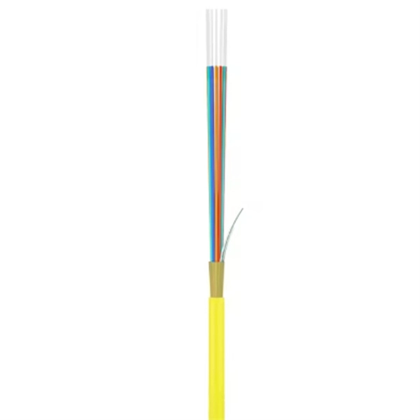
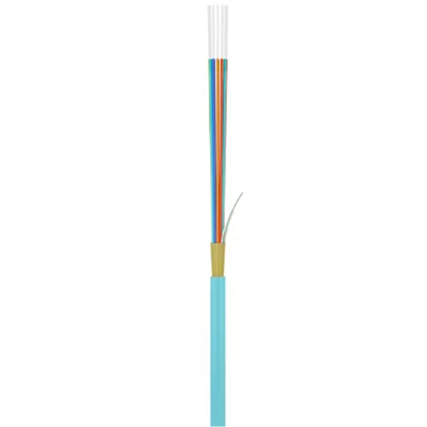
This guide covers the essential tools and step-by-step procedures for low-loss fiber optic cable repair. Fiber optic cable is strong, reliable and built for long-term performance, but it still needs to be handled correctly during installation. Most fiber damage does not come from normal operation after the system is live. It happens during installation, when excessive pulling force, tight bends. In today's hyper-connected world, fiber optic cables serve as the lifelines of high-speed data transmission, powering everything from global telecom networks to local FTTH (Fiber to the Home) systems. This article explores recommendations for pulling and installing fiber optic cable. Most fiber optic cables boast a pull strength of 100 – 200. While fiber optic cables are generally quite durable when correctly handled, defects and damage can happen. Cracks and breaks are of particular concern since they can cause data transmission to cease altogether. When these failures occur, they can cause costly network downtime. The Future Ready Solutions Tools & Test. Fiber optic cable cuts can be alarming, especially with problems like signals being dropped, internet interruptions, or even network failures. However, you don't need to panic! It can still be fixed. If you have the right tools and knowledge, you can definitely find the solution. Whether you have a.
[PDF]
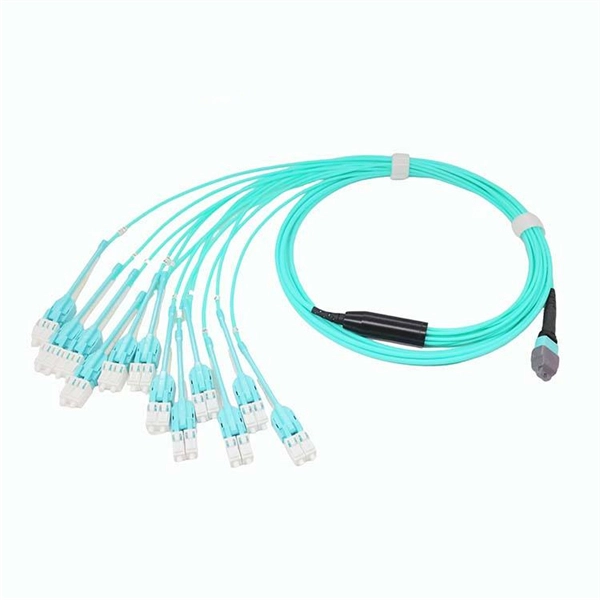
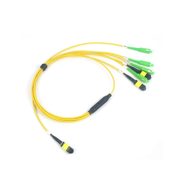
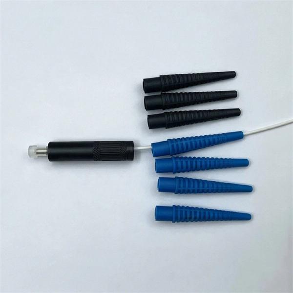
Fiber optic patch cables are ideal for supporting high speed telecommunication network fiber applications. They are manufactured and tested in compliance with TIA 604 (FOCIS), IEC 61754 and YD/T industry s.
[PDF]
This comprehensive guide provides step-by-step instructions for sizing electrical cables in accordance with Australian Standard AS/NZS 3008. Electrolytic Tough Pitch (ETP) : The workhorse for most applications - 99. 9% pure with oxygen molecules peppered throughout the structure. Offers optimal balance of conductivity and cost Oxygen-Free Copper (OFC) : Created in oxygen-free environments, eliminating oxide impurities. Has marginally. Selecting the correct cable size is not just about electrical efficiency—it is a critical safety requirement. Under-sized cables lead to insulation failure, fire hazards, and significant equipment damage. Whether you're an electrical engineer, contractor, or student, this resource will help you master the essential calculations for selecting the. The National Electrical Code (NEC) provides clear guidelines for ground wire sizing through Table 250. 122, but understanding how to apply these requirements correctly can make the difference between a safe installation and a costly code violation. Proper grounding conductor sizing is critical for. Professional electrical wire sizing tool based on National Electrical Code (NEC) standards. Calculate proper wire gauge, voltage drop, and ampacity for safe electrical installations. Input your electrical parameters to get accurate wire size.
[PDF]
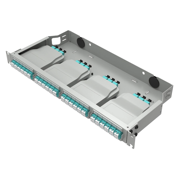
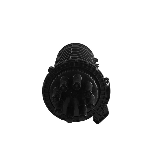
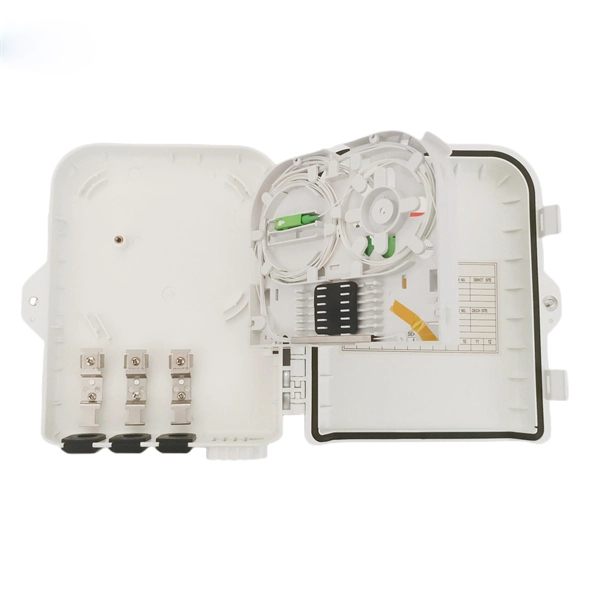
Proper fiber optic termination is a crucial process for ensuring the reliability, performance, and long-term durability of any fiber optic network. The process of fiber optic cable termination is the essential act of connecting fiber optic cables to devices, patch panels, or other. Fiber optic joints or terminations - where cables are terminated - are made two ways: 1) connectors that mate two fibers to create a temporary joint and/or connect the fiber to a piece of network gear (left) or 2) splices which create a permanent joint between the two fibers (right). Thus, you will put the cable across the points, stretch it to determine length, cut it accordingly, and place the connector on each end. After that, the patch panel attaches to it. Each cable has a connector attached. A. Once fiber optic cables have been successfully placed, we can focus on managing the ends of the fibers. This process depends on the project's needs and identifying a solution that aligns with the current situation. We can make suggestions that typically benefit the current circumstances and result. Where copper twisted pairs tend to terminate with an RJ45 plug, fiber optic connectors come in all sorts of shapes and sizes, with all manner of different use cases in mind. An optical fiber connector is used to join optical fibers where a connect/disconnect capability is required.
[PDF]
In this video, we'll walk you through the process of wiring a home distribution box with a detailed connection diagram. Whether you're an electrician or a DIY enthusiast, this guide will help you understand the basics of home electrical distribution. What is Distribution Board? Distribution board. An electrical panel box, also known as a breaker box or a distribution board, is a crucial component of any electrical system. It serves as a central hub for distributing electricity throughout a building, ensuring that power is delivered safely and efficiently to all the required locations. Distribution Board or DB is an electricity supply system or a common enclosure that distributes the electrical power feed into subcircuits. It includes isolator, RCCB (Residual current circuit breaker) or RCD (Residual-current device) devices, protective fuses or MCB's (Miniature Circuit Breaker). A distribution board or distribution box is where the main power supply is distributed to multiple loads. And all the switching and protective devices are installed in the distribution box. Single Phase Distribution Box generally consists of Double Pole MCBs, Single Pole MCBs, and RCCBs. In the following tutorial, we will show how to wire 120V single-phase and 240V split-phase circuit breakers and loads inside a residential main panel. The figure below shows a typical breaker panel used for 120V and 240V circuits. Three conductors enter the main panel from the energy meter and main.
[PDF]
Practice good wiring: secure grounding, neat cable management, proper insulation, and correct wire gauge and breaker size. Include protection devices like breakers, fuses, and surge protectors—each circuit should have its own protection. Comply with standards: Follow NEC, IEC . We'll show you how to run the wires, install the proper jacks and hook up the central distribution box. The new system doesn't mean you have to scrap your old cables and jacks. Existing phone lines and jacks can coexist with your new communication wiring system. We recommend that you initially. Learn how to wire a distribution box step by step! This video shows real on-site footage of electrical installation, demonstrating safe and standardized wiring methods used by professionals. And all the switching and protective devices are installed in the distribution box. Single Phase Distribution Box generally consists of Double Pole MCBs, Single Pole MCBs, and RCCBs. It is usually equipped with circuit breakers, fuses, terminal connectors, and other components. It is mainly used to isolate fault circuits, prevent overload, and ensure the safe operation of. Material preparation: Prepare the required circuit breakers, wires, wiring ties and other materials, and ensure that they meet the design drawings and installation requirements. Location determination: Determine the installation position of the circuit breaker according to the position of the.
[PDF]
Glass fiber and plastic fiber is fragile. When individual fibers break, light transmission and uniformity are reduced. After the first few fibers break at a stress point, a chain reaction occurs, hastening t.
[PDF]
This video shows real on-site footage of electrical installation, demonstrating safe and standardized wiring methods used by professionals. more Learn how to wire a distribution box step by step!. A distribution box, also known as an electrical distribution board, is a critical component in electrical systems. It serves as a central point for distributing electricity to various circuits in a building or facility. It has three categories: residential, commercial and industrial electrical distribution boxes, all of which play important roles in their respective electrical. In modern electrical systems, cable distribution boxes (also known as electrical distribution boxes or distribution boxes) play a crucial role as the key hub for managing, distributing, and protecting circuits. What is the role of the electrical panel? It's also called the breaker box or distribution board. It's the central hub that divides main service lines into smaller branch.
[PDF]
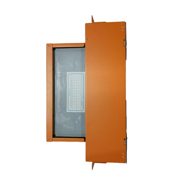
A cable tray serves to group and support cables, allowing for their routing to a specific destination. However, it does not provide mechanical protection. A trough accomplishes a similar purpose but is enclosed, thus providing mechanical protection for wires that would otherwise be. We'll look at the main types of cable supports, what makes them different, and when to use each one. My goal is to help you pick the right solution for your electrical wiring needs. When we talk about cable trays, we're usually thinking about open or semi-open structures that hold and guide cables. Although both cable tray and wireway perform the same function, there are significant differences between the two that are worth understanding. In this article, we'll delve into what cable trays and wireways are, how they differ, and what factors to consider when choosing between them. What is a. This is the role of the cable tray system—a structured framework designed to support and organize insulated electrical cables, control cables, and communication lines. Cablofil steel trough trays provide the strength and security required when then need to limit cable access is of primary importance. Cablofil steel trough trays.
[PDF]
Classes 1, 2, 3, and 4, communications, fire alarm, and optical fiber cables are all addressed in the NEC. Several changes related to communications cables have received the green light to be included in the 2023 National Electrical Code. Nuclear Regulatory Commission (NRC) is issuing for public comment a draft Regulatory Guide (DG), DG-1427, “Qualification of Fiber-Optic Cables, Connections, and Optical Fiber Splices for Use in Safety Systems for Production and Utilization Facilities. ” DG-1427 is newly proposed Revision 0. The following links on this page are to Adobe Portable Document Format (PDF) files. To obtain a free viewer for displaying this format, see our Plugins, Viewers, and Other Tools. ms for Production and Utilization Facilities. By Stanley Kaufman, PhD, CableSafe Inc. and Ronald Tellas. This part provides guidance to Federal agencies on the implementation of the Buy America Preference applicable to Federal financial assistance set forth in part I of subtitle A, Buy America Sourcing Preferences, of the Build America, Buy America Act included in the Infrastructure Investment and.
[PDF]
A waxed cord, called lacing cord, is used for binding the conductors. The cord comes in two sizes; #6 is used for small or medium sized cables, #8 is used for larger cables. A shuttle on which the lacing cord can be wound makes it easier to handle the cord. Cable lacing is a method for tying wiring harnesses and cable looms, traditionally used in telecommunication, naval, and aerospace applications. This old cable management technique, taught to generations of lineworkers, is still used in some modern applications since it does not create. BM-Rosendahl is the global supplier of production equipment for lead-acid and lithium-ion batteries. The portfolio ranges from solutions and equipment for enveloping, sleeving, wrapping & stacking, cast-on-strap to the assembly of automotive, motorcycle, industrial, and e-mobility batteries. The invention provides an optical cable cabling and yarn binding method, an optical cable cabling method, an optical cable and communication equipment, and relates to the technical field of optical cable manufacturing. To achieve optimum binding process requires knowledge about both binder and material. This Standard may also apply to the Jet Propulsion Laboratory other contractors, grant recipients, or parties to agreements PR 8735. 2, Hardware Quality Assurance Program Requirements for Programs and Projects.
[PDF]