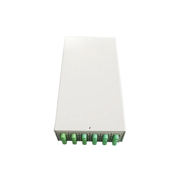
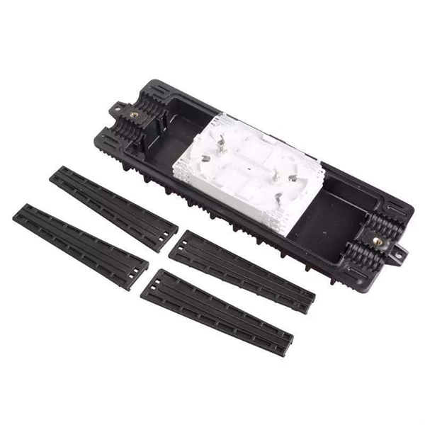
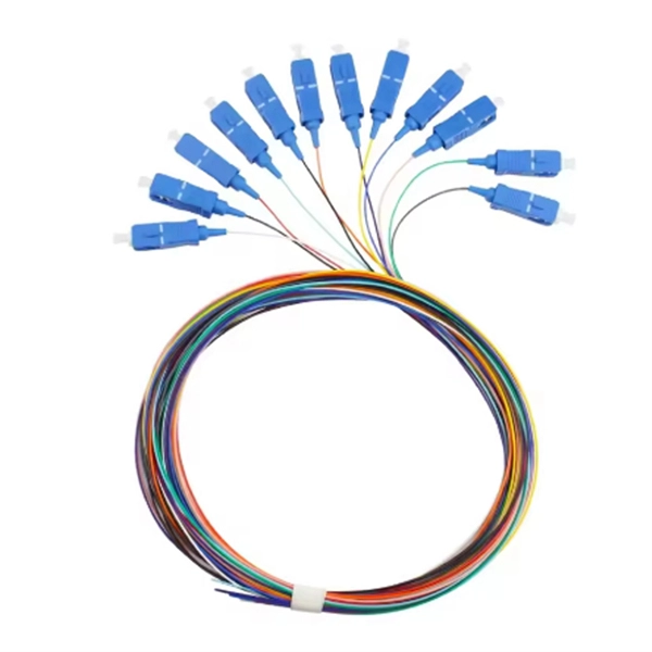
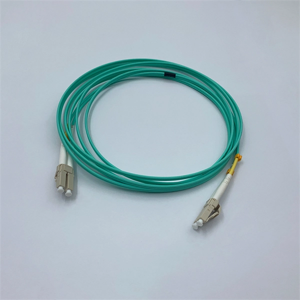
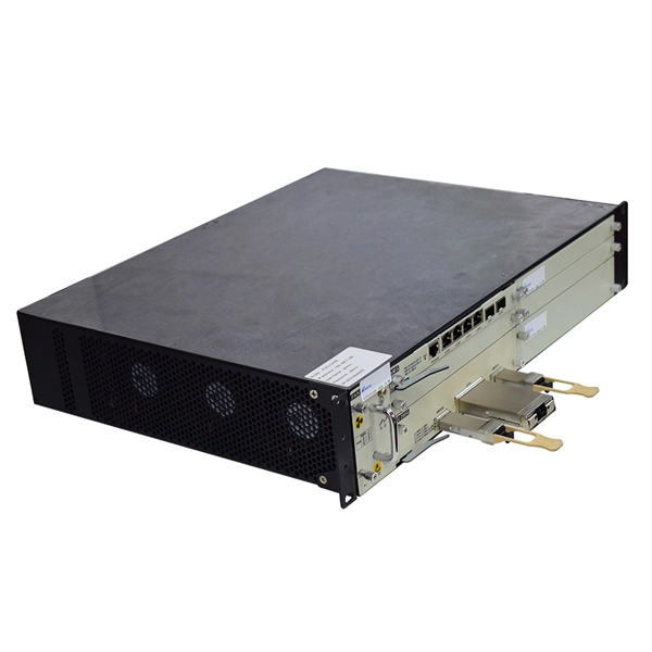
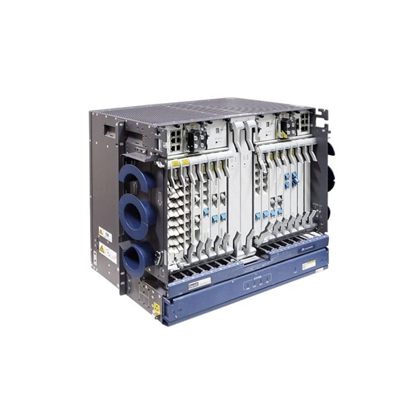
Fiber optic patch panels are enclosures that act as a distribution hub for fiber cable. A bulk (multi-strand) fiber cable enters the patch panel and then each fiber strand is separated into individual strands or pairs of strands. It acts as a hub for organizing splices and patch cords, streamlining fiber management and preserving signal integrity. These individual strands will then connect to electronic devices. A patch panel, including fiber patch panels and Ethernet patch panels, is a passive network device that centralizes, terminates, and organizes multiple copper or fiber cables. Serving as the interface between permanent cabling and active equipment, it provides clearly labeled ports that make. Structured cabling is a standardized system to help you organize and install the cables and hardware that connect your different devices to your network (including computers, servers, cameras, or any other smart gadgets). This article explores the structure, functionality, types, and benefits of fiber optic patch panels. What's the Fiber Optic Patch.
[PDF]
In this article, you will learn the step-by-step process of testing your solar panels using a multimeter. We will cover the essential tools you need, the specific measurements to take, and how to interpret the results. By the end of this guide, you will be equipped with the knowledge to diagnose. Solar panels are usually tested under standard conditions using a light source that mimics the light from the sun on a clear day. You can use the following method if you want to test your solar panel under standard conditions. Testing solar panels is easy with a multimeter! To test the current. Your multimeter is your best friend when testing solar panels. You can use it to check: Here's how: Multimeter — I recommend getting one that is auto-ranging. Also, a simple voltmeter won't work here. You need a multimeter that can measure both volts and amps. Locate the open circuit voltage. Learning to test a solar panel with a multimeter is an investment in your knowledge and ability to manage your own solar energy system or provide valuable services in the growing solar industry. Measure Voc (open circuit voltage) — if it reads 0V, the panel or wiring is dead. If it reads 60–80 % of rated, a bypass diode has failed. Perfect for DIY solar builders, RV owners, o. more Audio tracks for some languages.
[PDF]
Find detailed information on Electrical Equipment Manufacturing companies in Argentina, including financial statements, sales and marketing contacts, top competitors, and firmographic insights. Telconet, an Argentine company, specializes in high-technology equipment provisioning and offers structured cabling solutions for voice and data networks, which directly relates to the query about "Wire And Cable. Dun & Bradstreet gathers Electrical Equipment Manufacturing business information from trusted sources to. List of Electrical equipment suppliers in Argentina? There are 371 Electrical equipment suppliers in Argentina as of April, 2026. The highest number of Electrical equipment suppliers of Argentina are in Buenos Aires Province and Buenos Aires with 145 businesses and 56 businesses, respectively.
[PDF]

One-line diagrams and detailed network data (lines, transformers, buses). Short-circuit models, including fault current calculations under various system configurations. Protective relay settings and coordination curves. Historical. presentation of protection and control relaying. The report will identify methodology behind these practices, present issues raised by the integration of microprocessor relays and the internal logic and external communication configurations, ying. Schematic diagrams of protection relays are essential tools for power engineers in the power generation, transmission, and distribution industry. This includes AC schematics and DC schematics and diagrams that prominently feature relaying. There are other equally important types of drawings that are not the subject. Power System Protective Relays: Principles & Practices Presenter: Rasheek Rifaat, P. Eng, IEEE Life Fellow IEEE/IAS/I&CPSD Protection & Coordination WG Chair Jacobs Canada, Calgary, AB rasheek. com IEEE Southern Alberta Section PES/IAS Joint Chapter Technical Seminar - November 2016. Recognized under 2(f) and 12 (B) of UGC ACT 1956 (Affiliated to JNTUH, Hyderabad, Approved by AICTE - Accredited by NBA & NAAC – 'A' Grade - ISO 9001:2015 Certified) Maisammaguda, Dhulapally (Post Via. Kompally), Secunderabad – 500100, Telangana State, India To introduce all kinds of circuit.
[PDF]
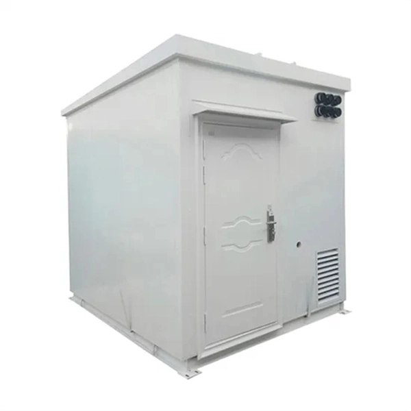
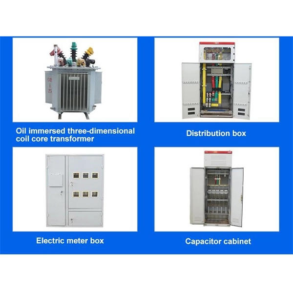
The main parts are the Miniature Circuit Breaker (MCB), Residual Current Device (RCD), busbars, and the main switch. Safe habits and checking the box often help stop electrical accidents. Learn about the main parts in a distribution box. These are MCBs, RCDs, busbars, and the main. A distribution box is a key part of electrical systems in buildings. Inside, you'll find parts like circuit breakers and fuses that protect the system from problems like overloads and short circuits. Today, electrical systems are essential for homes and industries. But what exactly is a power distribution box, and why is it so essential in our daily lives? The DB panel board controls the flow of electricity. Electrical systems power our homes, offices, and industrial facilities, but behind every reliable electrical setup lies a crucial component that often goes unnoticed: the distribution box. If you know. The internal structure of the distribution box is designed to safely distribute power from the main power source to multiple branch circuits. It provides convenience for protection, control and maintenance.
[PDF]
The standard requirement for wire is 1. 5 to 2 feet for each square foot of the home; however, it may change depending on the project scope, needs, and demands. Whether you're quoting a panel upgrade for a new build or wiring a multi-unit commercial space, the numbers on your estimate aren't just guesses—they're the difference between staying profitable and bleeding hours on change orders. This guide lays out what it really takes to build accurate. In May 2026 the estimated national average cost to Install Electrical Wiring starts at $302 - $365 per wiring run. Use our Cost Calculator for cost estimate examples customized to the location, size and options of your project. Set Project Zip Code Enter the. It's natural to wonder about the bottom line, and understanding the electrical wiring cost per foot is the perfect place to start. When installed by a professional, this cost typically lands somewhere between $3 and $12. Here are the five steps to create a competitive electrical estimate. Early preparation. In electrical projects, preparing a professional electrical quote is an essential yet often time-consuming task. Calculating material costs, labor fees, and profit margins for electrical projects can be challenging, especially when meeting client expectations or managing revisions. The kitchen and the laundry area are the most power-consuming parts of the house.
[PDF]
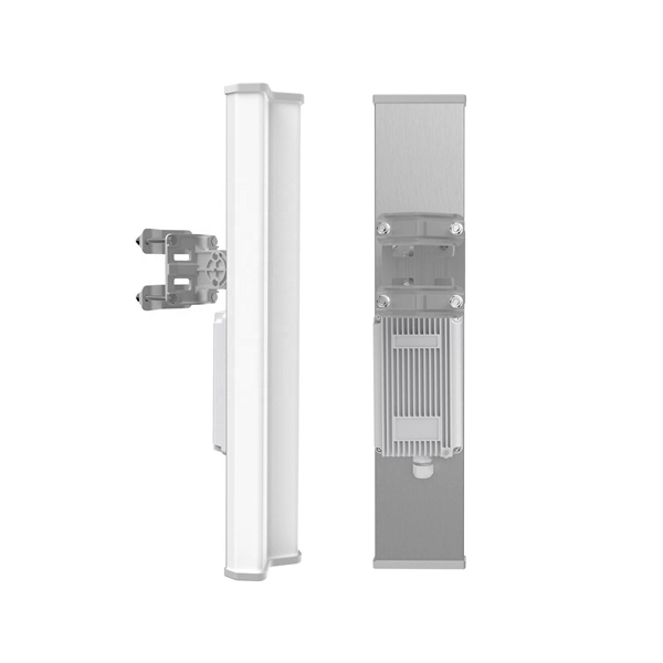
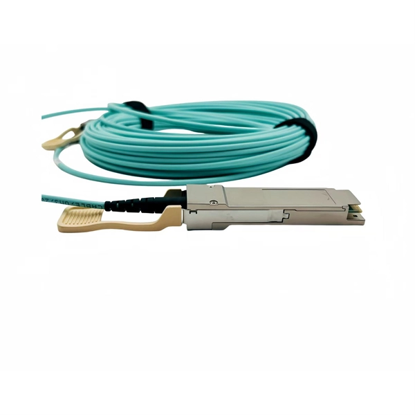
In this video, we take you through the step-by-step installation of Optical Distribution Frames (ODF) and Optical Fiber Patch Panels—key components in setting up a robust fiber optic network. At Eman Communications, we specialize in delivering high-quality installations that ensure opt. more In. Fiber optic patch panels are mostly mounted in 19 inch relay racks, but they can also be mounted on freestanding rails, in cabinets and also on walls. The fiber optical patch panel is convenient for people to easily access the optical fiber cable in the panel. Keeping this page as a placeholder for now. Have any questions? Talk with us directly using LiveChat. An ODF is a centralized platform designed for terminating, cross-connecting, and managing optical fibers. It ensures fiber management is structured, minimizes signal loss, and provides accessibility for maintenance and future expansion. ODF Rack/Cabinet: Physical frame housing all terminations and. To connect fiber optic cables to a patch panel, users must follow a specific procedure that ensures proper connectivity and signal transmission. Here is a step-by-step guide on how to connect fiber optic cables to a patch panel. Step 1: Gather the Tools and Equipment The first step in connecting.
[PDF]
Use this Protection Relay Setting Calculator to calculate pickup current, time multiplier settings (TMS), operating time, coordination time interval (CTI), and plug setting multiplier (PSM) using fault current, CT ratio, and IEC 60255 curve parameters. of protective relays in terms of protecting high voltage lines. At the beginn ng of the article it is drawn up process to protect power lines. Consequently, it is shown the method of calculation for a particular power line a d performed the calculation for setting the distance protection. These calculations are critical in industrial. ve reliable and properly coordinated relay settings. Protection coordination refers to the systematic arrangement and interaction of protective devices within an electrical distribution network to ensure that faults are isolated in a controlled and orderly manner. The. With the help of these spreadsheets below, you can make your endless calculations much easier! Contact us for more information and download:.
[PDF]
Relay protection is the discipline of designing schemes that detect faults, coordinate relays, and isolate equipment without outages. It emphasizes selectivity, coordination, fault response, and system behavior rather than individual relay devices. The main relay protection functions (overcurrent, directional, differential, distance, etc. ) and network communication systems (SCADA, RTUs, digital and analog inputs and outputs, IEC 61850, etc. ) are briefly explained in this technical article. Table of contents: 1. Protection systems Protection. Electromechanical protective relays at a hydroelectric generating plant. The relays are in round glass cases. The rectangular devices are test connection blocks, used for testing and isolation of instrument transformer circuits. In electrical engineering, a protective relay is a relay device. transmission line faults through the use of communication-assisted protective relaying. These conditions may include overloads, short circuits, or insulation failures. It functions as a watchdog by constantly surveying multiple system components including voltage, current, frequency, and phase angle.
[PDF]
Distance relays, also known as impedance relay, differ in principle from other forms of protection in that their performance is not governed by the magnitude of the current or voltage in the protected circuit but rather on the ratio of these two quantities.OverviewIn, a protective relay is a device designed to trip a when a is detected. The first protective relays were electromagnetic devices, relying on coils operating on moving par. Electromechanical protective relays operate by either, or. Unlike switching type electromechanical with fixed and usually ill-defined operating voltage thresholds. Electromechanical relays can be classified into several different types as follows: "Armature"-type relays have a pivoted lever supported on a hinge or knife-edge pivot, which carries a moving contact. These relays may.
[PDF]
The article provides an overview of protective relaying principles and their applications for high-voltage power system components. It covers the protection methods for generators, transformers, buses, and transmission lines using various relay types to detect and isolate. The rectangular devices are test connection blocks, used for testing and isolation of instrument transformer circuits. In electrical engineering, a protective relay is a relay device designed to trip a circuit breaker when a fault is detected. : 4 The first protective relays were electromagnetic. Currently resides in Orlando, FL and provides application consulting for engineers throughout the state. Proficient in all ABB/GE medium and low voltage distribution products. Also proficient in system modeling and studies with EasyPower and EMTP. Product Specialist (West Region) for Digital. IEEE/IAS/I&CPSD Protection & Coordination WG Chair Jacobs Canada, Calgary, AB rasheek. com IEEE Southern Alberta Section PES/IAS Joint Chapter Technical Seminar - November 2016 Protective Relays - Technical Seminar Nov 2016 - Copyright: IEEE 2 Abstract: Protective relays and devices. Protective relays can be classified based on their operating principle, construction, or function: 1. Based on Operating Principle Electromechanical Relays: Work using moving parts and electromagnetic forces (traditional relays). Static Relays: Use electronic components without moving parts.
[PDF]
This paper discusses some practical aspects of implementing single-pole tripping schemes in transmission-line protection. Implementation and techniques will vary in the design of protective relaying systems that i.
[PDF]
Definition of Protective Relay A protective relay is an automatic device that detects abnormalities in an electrical circuit and closes its contacts. This action completes the circuit breaker's trip coil circuit, causing the breaker to trip and disconnect the faulty section from the. Eaton's protective relays provide you with unique microprocessor-based devices that eliminate unnecessary trips, mitigate arc faults, protect motors and breakers, and provide system information to help you better manage your system. Our predictive diagnostic solutions include non-destructive testing. Here, Several circuit breakers in the fault current paths from the generators to the fault location have been tripped. Note that all generators- the power sources – have been disconnected. Therefore, the whole system has gone down, even though many circuit breakers have remained closed. The relay continuously monitors electrical parameters such as current, voltage, frequency, and phase angle. When these parameters deviate from normal operating conditions or. The rectangular devices are test connection blocks, used for testing and isolation of instrument transformer circuits. : 4 The first protective relays were electromagnetic. Protective Relays - Technical Seminar Nov 2016 - Copyright: IEEE 2 Abstract: Protective relays and devices have been developed over 100 years ago to provide “lastline”of defense for the electrical systems.
[PDF]
Then, according to the short-circuit current parameters, the relay protection of transmission lines, transformers, busbars, etc. is set, and the configured protections include current quick-break protection, gas protection, and longitudinal differential protection. Generator protection covers: phase-to-phase short circuits in stator windings, stator ground faults, inter-turn short circuits in stator windings, external short circuits, symmetrical overload, stator overvoltage, single- and double-point grounding in the excitation circuit, and loss of excitation. Explore principles and configurations of protective relaying in high voltage systems. Ensure fast, selective fault clearance per IEC/IEEE standards. Abstract: In this paper, the main electric wiring mode of 110kV. Relay protection is essential to ensure the stability, reliability, and safety of electrical power systems. In HV (High Voltage) and MV (Medium Voltage) substations, relay protection safeguards critical assets such as transformers, circuit breakers, and lines. Effective relay protection depends on. A protection relay is an intelligent device used to monitor electrical parameters such as current, voltage, frequency, and phase angle. Finally, a comprehensive.
[PDF]
Its main purpose is to safeguard electrical equipment like transformers, generators, and transmission lines from damage due to abnormal conditions such as overloads, short circuits, or voltage imbalances. A protective relay is an intelligent electrical device designed to detect faults in power systems and initiate corrective actions such as tripping a circuit breaker. It initiates the operation of circuit breakers to isolate the affected section. This prevents damage to equipment, reduces. Transmission lines are a vital part of the electrical distribution system, as they provide the path to transfer power between generation and load. Transmission lines operate at voltage levels from 69kV to 765kV, and are ideally tightly interconnected for reliable operation. In other words, the prime function of protective relays is the timely and. Many important issues, such as coordination of settings, operating times, characteristics of relays, mutual coupling of lines, automatic reclosing, and use of communication channels, are examined. Special protection systems, protection of multi-terminal lines, and single-phase tripping and. In electrical engineering, a protective relay is a relay device designed to trip a circuit breaker when a fault is detected.
[PDF]