Los sensores de luz presentan una variedad de dimensiones, desde modelos compactos ideales para aplicaciones domésticas hasta sensores más grandes diseñados para entornos industriales. Estas dim.
[PDF]
Resolving these issues involves steps like checking cable connections, soft resets, updating firmware, and specific solutions for different router brands like ASUS and Spectrum. It often indicates that something is wrong with your internet connection or the device itself. Fortunately, diagnosing and resolving these issues doesn't have to be complicated. In this comprehensive guide, we will walk you through the common causes of a red light on your router and provide. A router showing a red light can mean different things, like a service outage, misconfiguration, or loose connection, all of which can lead to a broken internet connection. Fortunately, there are heaps of ways to fix a red blinking light on your router. One of the first things you should try is to. Turn off the router and disconnect the power cord. Check that the PON cable is free from damage or sprains. Even if you have the best router, you may experience a loss of connection or other issues and see that dreaded red light. When it's green and steady, everything is fine. However, when it blinks red or stays solid red, it signifies a Loss of Signal, a problem preventing your router from communicating.
[PDF]
Long-pass dichroic beam splitters are designed to transmit longer wavelengths of light and reflect shorter wavelengths, while short-pass dichroic beam splitters do the opposite. While this type of beam splitter is less common, it can be useful for fluorescent applications, such as. A beam splitter or beamsplitter is an optical device that splits a beam of light into a transmitted and a reflected beam. It is a crucial part of many optical experimental and measurement systems, such as interferometers, also finding widespread application in fibre optic telecommunications. In its. Beamsplitters are optical components used to split incident light at a designated ratio into two separate beams. Additionally, beamsplitters can be used in reverse to combine two different beams into a single one. Newport offers a wide variety of Beamsplitters in various shapes. a laser beam) into two (or sometimes more) beams, which may or may not have the same optical power (radiant flux). These plates are typically made of high-quality glass coated with a thin, anti-reflective film. The coating helps to minimize issues with annoying back reflections, such.
[PDF]
The AOI impacts the amount of light being reflected and transmitted. For example, most plate beam splitters have an AOI of 45 degrees, which may limit those who need more flexibility. A beam splitter or beamsplitter is an optical device that splits a beam of light into a transmitted and a reflected beam. It is a crucial part of many optical experimental and measurement systems, such as interferometers, also finding widespread application in fibre optic telecommunications. a laser beam) into two (or sometimes more) beams, which may or may not have the same optical power (radiant flux). Their precision and versatility make them indispensable in a variety of scientific, industrial, and technological applications. Beamsplitters are often classified according to their construction: cube or plate. Beamsplitters are fundamental components in optical engineering, serving to precisely divide a single input beam of light into two distinct output beams. This division allows for the simultaneous analysis or utilization of the light's properties along two separate paths. The device is purely. The beam splitter splits and then recombines infrared radiation, while the detector picks up the resulting signal. It's sensitive to both intensity and frequency. Together, they decide just how accurately an instrument captures those unique infrared “fingerprints” from different substances.
[PDF]
The Light Cube can be dyed using any color cube. Upon merging, it adopts the color of the cube used. Each dye attempt increases a dye counter, tracking how many times it's been recolored. 💡 Note: These items transform when fused with a Light Cube. The glow effect varies based on dye count. or if you want to see a video, then here: https://www. Each dye. This is a light cube DIY kit that you need to weld and assemble by yourself. The bottom plate comprises a circuit board and component parts. The 512 LED lights make up a stereo space. A variety of cool model showing a three-dimensional effect. It's better to watch in the night. Installation Manual:. 8x8x8 LED Cube Kit DIY Electronic Kit Soldering Project Kit, User Needs to Solder The LED, and The Displayed Content Can Be Modified. (GZT-64) Shop products from small. The dot matrix component features 25 RGB color light clusters, arranged in a 5x5 grid. Each individual light bead offers 16000K color variations, all of which can be controlled via an APP. When these 25 light beads come together, they provide an infinite array of color possibilities. It can craft some pretty decent weapons and it can make my favorite structure, Lantern! I hope you enjoy! :D. A light source has been placed inside to create interesting shadows. The pieces in this project can connect to each other without using any glue (however using glue.
[PDF]
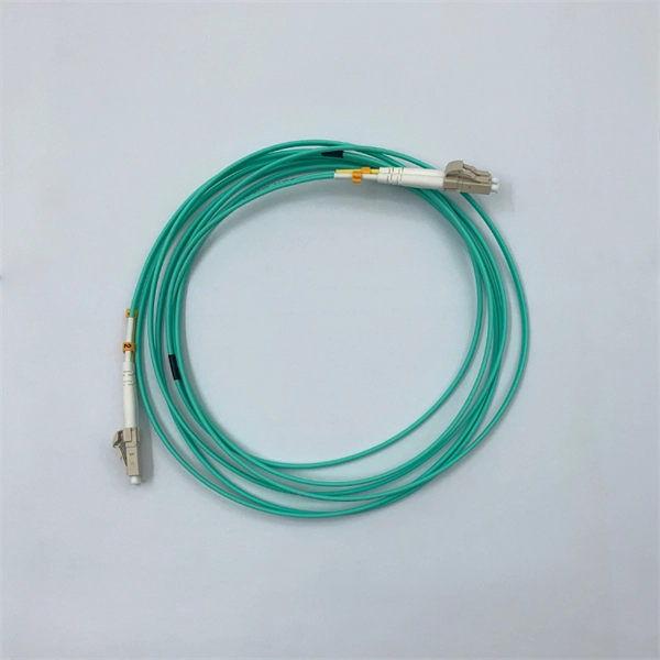
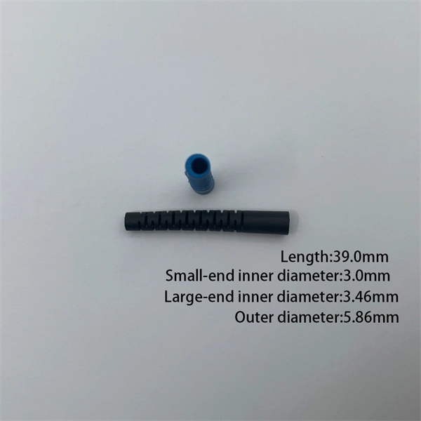
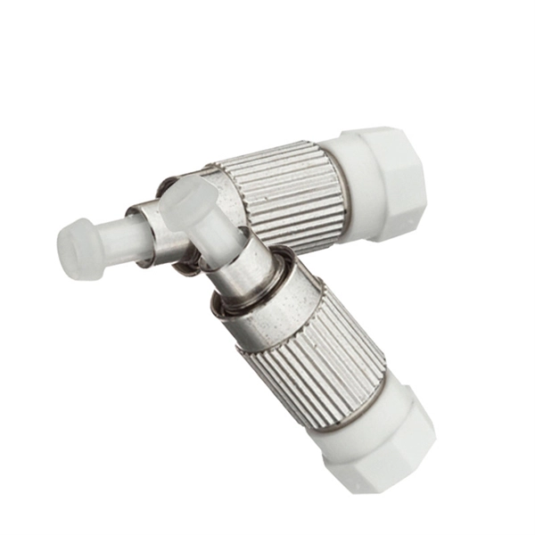
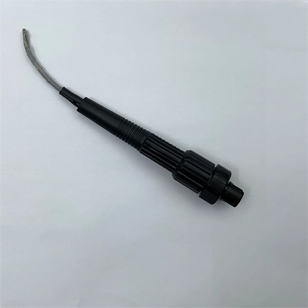
A pigtail connector is a short length of wire with a factory-terminated connector on one end and bare, exposed wires on the other. It serves as a bridge, allowing technicians to repair specific connection points without disturbing the rest of the system. These connectors can be a big help when you need to connect two wires, repair damage, or extend a. This is where the pigtail connector becomes an essential solution. What Is a Pigtail Connector? Types and Applications A pigtail connector is a short cable with a connector on one. Whether you're replacing an outlet or adding a new fixture, knowing when and why to use a pigtail can save you time and prevent potential hazards. It's a small detail with a big impact on your electrical setup. Let's learn more from this blog! What Is A Pigtail In Electrical Wiring? A pigtail in. Fiber pigtails are simple in appearance, yet essential in function. They are the bridge between fiber optic cables in the field and the equipment or patch panels that manage them. By combining factory-installed connectors with spliced bare fiber, pigtails ensure that network installers can create. A pigtail connector is a short, pre-terminated length of cable with one end connected to a connector and the other end left open or spliced into another assembly. It allows easy integration of connectors into systems where direct termination is difficult. Pigtails are widely used in RF, fiber.
[PDF]
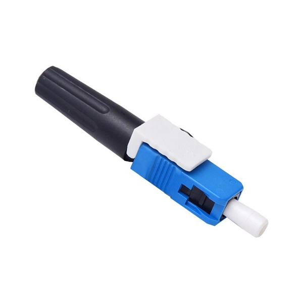
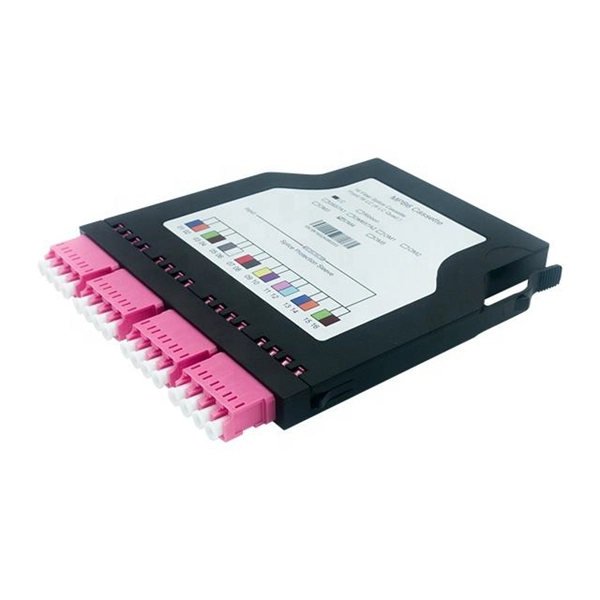
When you build or upgrade a fiber network, the same four words pop up everywhere— fiber optic (bare fiber), pigtail, patch cord, optical cable. They're related, but they are not interchangeable. Mixing them up drives costs higher, increases loss, and slows your rollout. The good news? Once you nail. Executive Summary: A fiber optic pigtail is one of the most commonly specified yet least understood components in structured cabling. Get the wrong connector type, the wrong polish, or skip proper fusion splicing technique—and you're looking at elevated signal loss, increased back reflection, and a. What is Fiber Pigtail? A Complete Guide for Beginners What is Fiber Pigtail? A Complete Guide for Beginners A fiber pigtail is typically a fiber optic cable with one end factory pre-terminated fiber connector and the other exposed fiber. It is usually suitable for field termination using a. The difference between patch cords, trunk cables, and pigtails is not just terminology — each serves a distinct role in installation, testing, maintenance, and cost management. This article explains their construction, typical use-cases, performance implications, and practical guidance so you can. A fiber optic pigtail is a short-length cable with a pre-terminated connector on one end and a bare, unterminated fiber on the other. Its primary role is to connect multi-core fiber cables (e., 12-core, 24-core) to patch panels, ODFs, or devices via fusion splicing.
[PDF]
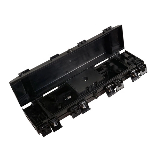
A fiber to Ethernet converter, often called a media converter, is a networking device that converts light signals from fiber optic cables into electrical signals used by Ethernet cables. This allows you to connect devices that use different types of cabling, such as a computer. An ONT, or Optical Network Terminal, is a device that converts fiber optic signals from your Internet provider into Ethernet signals that your devices can use. It's a key part of any Fiber to the Home (FTTH) setup. If your home uses cable Internet instead of fiber, you don't need an ONT. You'll use. For networking scenarios where the standard 100-meter reach of copper Ethernet cables (UTP or STP) is insufficient, Ethernet media converters for extended distance connectivity present a professional solution to extend connectivity. Connection Relationship: Step 1: Access outdoor fiber optic cables into fiber terminal box for the purpose of splicing the optical fiber cable and fiber optic.
[PDF]
Light decay in light divisions refers to the decrease in light intensity as it travels through optical fibers or other transmission media. This decay can occur due to a number of factors, including absorption, scattering, and reflection. If you don't know what kind of losses to expect in your system, you won't know how many other components. It is also known as fiber loss or signal loss. The signal attenuation of fiber determines the maximum distance between transmitter and receiver. Another important property of optical fiber is. Fiber loss, also called fiber optic attenuation or attenuation loss, refers to the loss of signal between input and output. Losses can be introduced by various means such as intrinsic material absorption, scattering, bending, connector loss and more. This loss can significantly reduce the effectiveness of optical fibers in applications such as telecommunications, imaging systems, and even simple fiber-optic tools like flashlights. In the early days of.
[PDF]
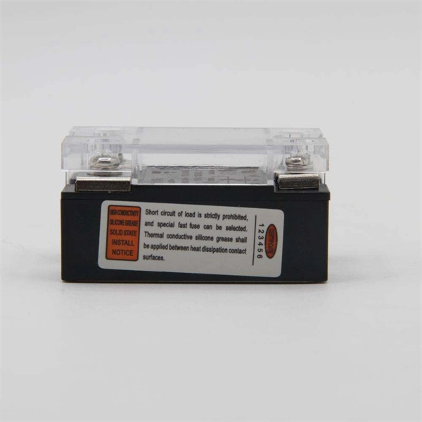
Check the electrical load and ensure that the sensors do not exceed the 10 Amp maximum. Check each wire for damage that may lead to a short. Check the following: Check if all cable connections are tightened with a torque moment of 14Nm (17Nm for the M10 model). Check if the surface area. Channel has NO voltage and there is an active fault. Check for tripped or missing circuit breaker Sticky fault on the channel. Sticky Fault - an indicator that a fault has occurred that will stay until the indicator has been cleared manually. Channel has NO. Each powernet distribution box (PNDB) on the vehicle provides up to 4 low amperage circuits (30 amp and less), and up to three high amperage circuits through midi fuses. The fuses are located behind a cover on the face of the PNDB. On vehicles equipped with a cab load disconnect switch (CLDS), the. I have the following issues, green light on shunt all red lights on distributor, no SOC on screen. Everything else is working great. In troubleshooting I removed all the fuses from the distributor just to see if the fuse lights would not illuminate red and get green power. Any. Show the control box indicator lights. Show the accessory response (or lack of response). For LED Light Kit issues, also provide a photo of the LED Y-cable (to confirm which version you have). Videos and photos are required to file warranty claims with the manufacturer.
[PDF]
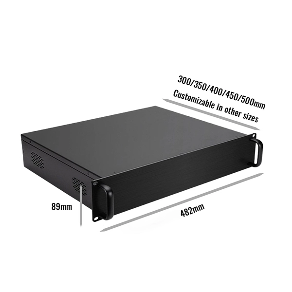
This video shows real on-site footage of electrical installation, demonstrating safe and standardized wiring methods used by professionals. In this guide, we'll break down everything you need to know to install a distribution box correctly and confidently. Choose the right box based on environment (indoor/outdoor), load capacity, and durability. Check for proper IP/NEMA ratings and material quality. A distribution board or distribution box is where the main power supply is distributed to multiple loads. And all the switching and protective devices are installed in the. An electrical panel box, also known as a breaker box or a distribution board, is a crucial component of any electrical system. more Learn how to wire a distribution box step by step! This video shows real on-site footage of. Material preparation: Prepare the required circuit breakers, wires, wiring ties and other materials, and ensure that they meet the design drawings and installation requirements. It has three categories: residential, commercial and industrial electrical distribution boxes, all of which play important roles in their respective electrical.
[PDF]
This guide will provide you with a detailed Cat 6 socket wiring diagram, outlining the necessary steps and components required for a successful installation. If you want to install a classic network socket, you must first strip the Cat. A special stripping tool for data cables is used here – for example, the Stripper No. Use side A to remove the protective jacket. 35, you can shorten the network cable (Cat. 7) a little bit, if required. If you have too much cable left, it will be harder to. Learn how to wire a distribution box step by step! This video shows real on-site footage of electrical installation, demonstrating safe and standardized wiring methods used by professionals. 5mm² wires, and the air conditioning circuit can use 2. Connection method: Each switch takes a wire from the incoming point and connects it to the incoming end of the switch, or uses parallel connection to reduce the difficulty. Learn how to install a distribution box safely and correctly. Covers wiring, placement, standards, and expert tips for a compliant setup. A distribution box is the heart of any electrical system. It takes the incoming power and safely distributes it to different circuits throughout your building. Understanding the wiring diagram of an electrical panel box is essential for electricians and homeowners alike, as it allows them to troubleshoot any electrical issues, carry out repairs, or make additions to the system.
[PDF]
How to punch down Cat5e, Cat6 or Cat7 cable to a keystone jack with RJ45 ethernet wall socket for your network cables. more How to Wire Up Ethernet Plugs WITHOUT special tools!! (Tool Free RJ45 Connector for CAT5e & CAT6). Ref: What are the requirements for a Home Network? Cable – For home networks cat 6 is probably the best choice today. CAT 7 (latest version) is shielded which adds complications to the installation. Solid vs stranded cable – See here. For backbone cabling use solid. RJ45 Connectors -Terminates the. It takes the incoming power and safely distributes it to different circuits throughout your building. Whether in a home or an industrial facility, this box keeps your electrical setup organized, functional, and efficient. However, the key to a safe and reliable system lies in proper installation. Download free collection of AutoCAD details for electrical systems. All installation details for electrical design of building including the various systems in electrical field such as power distribution, lighting, earthing, electrical cables, distribution boards and many other electrical system. Network cabling installation forms the critical backbone that determines your business's connectivity reliability, data transmission speeds, and scalability potential. Having a wired network allows me to have a private, high speed, network at home.
[PDF]
In fiber-optic communications, wavelength-division multiplexing (WDM) is a technology which multiplexes a number of optical carrier signals onto a single optical fiber by using different wavelengths (i.e., colors) of laser light. This technique enables bidirectional communications over a single strand of fiber (also called wavelength-division duplexing) as well as multiplication of capacity. The. SystemsA WDM system uses a at the to join the several signals together and a at the to split them apart. With the right type of fiber, it is possible to have a device that does both s. Originally, the term coarse wavelength-division multiplexing (CWDM) was fairly generic and described a number of different channel configurations. In general, the choice of channel spacings and frequency in these co.
[PDF]
Your eyes contain two types of light-sensing cells: rods and cones. Rods detect low-light vision and motion, while cones handle color vision and detail in bright light. Damage to either can lead to vision problems like night blindness or color blindness. Protecting your eyes with proper nutrition. Personnel Safety. Optical Touch Buttons. Self-contained Sensors. Each technology has unique strengths and weaknesses, so the requirements of the application itself will determine what technology should be used. This article is focused on photoelectric sensors and defines what they are, their adv ors are readily present. Quality Control: They can detect defects, ensure proper product placement, and verify the presence of components. Safety: They can be used to create safety barriers, preventing machinery from operating when a person or object is in a hazardous zone. In this section, we explore the geometric optics of the eye. Early thinkers had a wide array of theories regarding vision. Euclid and Ptolemy believed that the eyes emitted rays of light;. Understanding the eye involves examining how its individual parts contribute to the overall function. Vision begins as light enters the eye through the cornea, a transparent, dome-shaped outer.
[PDF]