A WDM system uses a multiplexer at the transmitter to join the several signals together and a demultiplexer at the receiver to split them apart. With the right type of fiber, it is possible to have a device that does both simultaneously and can function as an optical add-drop. In fiber-optic communications, wavelength-division multiplexing (WDM) is a technology which multiplexes a number of optical carrier signals onto a single optical fiber by using different wavelengths (i., colors) of laser light. This technique enables bidirectional communications over a. WDM is a fiber optic transmission technique that leverages multiple light wavelengths to transmit data efficiently over a single medium. WDM technology employs different optical wavelengths, or colors, of laser light to multiplex several optical carrier signals onto a solitary optical fiber. Each. There are a lot of people who don't understand the difference between WDM and optical splitter. This allows multiple channels of data to be transmitted simultaneously. WDM technologies allow organizations to place equipment at either end of a fiber pair and combine multiple wavelength channels on a single fiber pair instead of using multiple separate fibers pairs for every separate service. The article explains the fundamental principle and its.
[PDF]
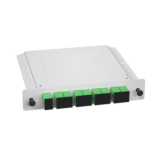
Planar waveguide optical splitter (PLC Splitter) is a kind of integrated waveguide optical power distribution device based on quartz substrate, which has the characteristics of small size, wide working wavel.
[PDF]
Also, please take a look at the list of 18 fiber optic splitter manufacturers and their company rankings. YINGDA TECHNOLOGY LIMITED, 2. Shenzhen Spring Optical Communication Co. What Is a Fiber Optic. PPC Broadband offers a range of optical splitters designed for various applications, including indoor and outdoor use. Their expertise in fiber solutions for telecommunications ensures high-quality performance in connectivity technology. T&S Communications specializes in optical network. The global market for Optical Splitter was estimated to be worth US$ 698. 9 million in 2023 and is forecast to a readjusted size of US$ 1021. 5% during the forecast period 2024-2030 China is the largest producer of Optical Splitter, with a market share about 50%. Whether you're a homeowner upgrading your FTTH setup or a small business installing a new fiber network, knowing the best brands, their popular products, and pricing can help you make an informed decision. By comparing these factories, you'll discover the best quality and value. Dive in to find out which options can elevate your connectivity experience! Fiber Optic Splitters – Maxcom, Inc. Contract manufacturing services are also offered. Suitable for micro-electromechanical systems (MEMS). Distributor of fiberoptic equipment including splitters.
[PDF]
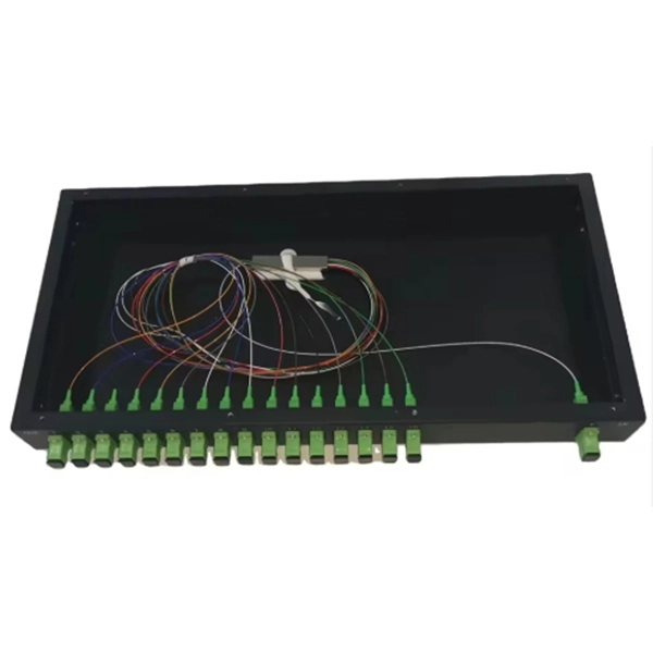
By dividing a single optical signal from a central Optical Line Terminal (OLT) into multiple outputs for Optical Network Terminals (ONTs) at users' homes, splitters eliminate the need for dedicated fibers to each residence—slashing infrastructure costs while scaling network reach. Understanding Fiber Optic Splitters: Principles, Parameters, Types, Applications, and Future Trends 1. Introduction Fiber optic splitters are integral components in the world of optical networks. They are devices that split an incident light beam into several light beams at certain splitting. The PLC optical splitter (Planar Lightwave Circuit splitter) is one of the most widely used passive components in modern optical communication systems. A fiber optic PLC splitter distributes a single optical signal into multiple outputs with high uniformity and low loss, making it ideal for. Optical splitter is a core passive device in FTTH system. Fiber splitters can effectively split optical signals into. Fiber optic splitters are essential passive devices in modern optical communication systems, enabling the division of a single light signal into multiple outputs or combining multiple signals into one. It is a crucial part of many optical experimental and measurement systems, such as interferometers, also finding widespread application in fibre optic telecommunications.
[PDF]
A beam splitter or beamsplitter is an optical device that splits a beam of light into a transmitted and a reflected beam. It is a crucial part of many optical experimental and measurement systems, such as interferometers, also finding widespread application in fibre optic telecommunications. DesignsIn its most common form, a cube, a beam splitter is made from two triangular glass which are glued together at their base using polyester,, or urethane-based adhesives. (Before these synthetic,. Beam splitters are sometimes used to recombine beams of light, as in a. In this case there are two incoming beams, and potentially two outgoing beams. But the amplitudes. For beam splitters with two incoming beams, using a classical, lossless beam splitter with Ea and Eb each incident at one of the inputs, the two output fields Ec and Ed are linearly related to the inputs thro.
[PDF]
The centralized splitter approach typically uses a 1×32 splitter in an outside plant (OSP) enclosure, such as a fiber distribution terminal. The 1×32 splitter is directly connected via a single fiber to an OLT in the central office. They are typically installed in each optical network between the PON OLT (optical line terminal) and ONTs (optical network terminals) that the OLT serves. Generally, two kinds of fiber optic splitters are popular, which are FBT splitters and PLC splitters. The differences between the two have been. A fiber broadband provider typically determines and overall split ratio for the network, such as 1x32 or 1x64, and uses combinations of splitters to meet that ratio with each PON port. 1x32 splits were common in North America for G-PON architectures. As XGS-PON continues to be adopted, some service. This comprehensive guide explains how optical splitters work, what types are available, and how to select the optical splitter best buy or optical cable splitter best buy for your network deployment. What Is a Fiber Optic Splitter? A fiber optic splitter is a passive optical component designed to. Star couplers are used for their uniform splitting, while WDM splitters are used to split light beams of different wavelengths. Application Areas Fiber optic splitters are used in various areas, including active optical networks, passive optical networks, FTTX access networks, and measurement.
[PDF]
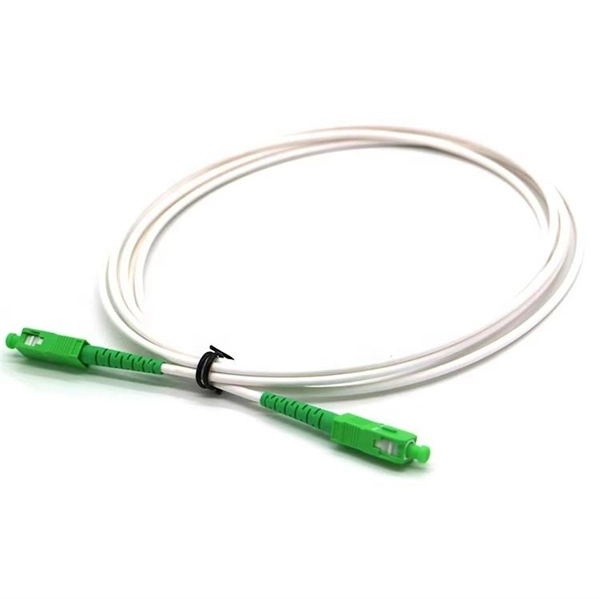
A PLC splitter is a passive optical device that divides one incoming optical signal from an input fiber into multiple output signals across several output fibers. PLC splitters utilize a planar lightwave circuit chip made of silica glass waveguides to distribute the optical power. PLC optical splitters (planar waveguide optical splitter) is a key component in optical fiber communication networks and is widely used in optical fiber distribution systems such as FTTH (fiber to the home) and PON (passive optical network). This passive yet sophisticated device utilizes integrated optics technology to split a single input signal into multiple. PLC splitter, also called Planar Waveguide Circuit splitter, is a device used to divide one or two light beams into multiple light beams uniformly or combine multiple light beams to one or two light beams. This helps share signals in fiber optic networks. Pick the split ratio that matches what you need. Lower ratios work for fewer users. Choose the connector type like SC, LC, or FC.
[PDF]
XGS-PON is a 10 Gbps symmetric passive optical network (X=10, S=symmetric). Optical fiber's greater transmission capacity and speed deliver upstream and downstream (symmetric) speeds of up to 10 Gbit/s (gigabits per second) on the road to connecting users in the last. 10G-PON (also known as XG-PON or G. 987) is a 2010 computer networking standard for data links, capable of delivering shared Internet access rates up to 10 Gbit/s (gigabits per second) over optical fibre. This is the ITU-T 's next-generation standard following on from GPON or gigabit-capable PON. It is commonly used to implement the link to the customer (the last kilometre, or last mile) of fibre-to-the-premises (FTTP) services, using a. Short on Ethernet ports and looking to connect an extra device or two to your wired network setup? You're likely to encounter two options: an Ethernet splitter, and an Ethernet switch. Here's why you should choose the switch every time. What Is an Ethernet Splitter? An Ethernet splitter is a simple. Recommendation ITU-T G. 1 describes a flexible optical fibre access network capable of supporting the bandwidth requirements of business and residential services and covers systems with nominal line rates of 2. 4 Gbit/s in the downstream direction and 1. 984 G-PON and ITU-T G. 9807 XGS-PON wavelengths to coexist within the same single mode fiber cabling and across the same passive optical distribution splitters. This means that users can.
[PDF]
Connect the Optical Source: Using an optical (TOSLINK) cable, connect your source device's Optical Out to the splitter's SPDIF Input. 1-Input, 3-Output Optical Audio Splitter allows users to send their optical spdif/toslink audio signal to three separate destinations simultaneously. Incorporate your new soundbar, AV receiver or wireless headphones into your existing setup easily with the JTDSP0103. This is ideal for sending audio from one source (Blu-ray player, game console, TV, streamer, etc. ) to multiple audio. Optical splitters offer a cost-effective and dependable solution across various fiber optic applications. Also known as optical splitters, fiber splitters, or beam splitters, these devices are integrated waveguides ensuring wide bandwidth and minimal loss in high-frequency applications. We'll also share tips to minimize signal loss and ensure optimal performance. What Is a Splitter and Why Cascade Them? A splitter divides a single input signal into. There are primarily two methods to split optical audio signals: 1. This method is simple and effective, provided certain considerations are taken into account:.
[PDF]
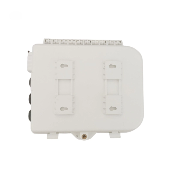
This video provides a step-by-step guide on how to efficiently install optical splitter into a fiber terminal box, demonstrating a professional and reliable deployment for optical distribution network solution ( https://www. com/c/optical-distribu. The following is a guide to installing and using a fiber optic splitter, including key steps and precautions: Required tools: Fiber cleaver, wire stripper, alcohol wipes/cleaning pen, optical power meter. Splitter Type: Choose a PLC type (uniform splitting) or an FBT type (non-uniform splitting). This adapter effectively provides Ethernet data and DC power to a non-PoE device with a single cable and allows it to operate within a PoE network. PoE is an efficient and convenient solution for remote applications where available space is limited and/or no power source is readily available. This manual provides safety and installation instructions for the 9490-OS Fiber Optic Passive Splitters. All units use type LC connectors and vary only in the splitting fan-out, and as single or dual-channel capability as listed below. All units are entirely passive and require no frame power or. After installing the mounting box or bracket, feed the 4-pair UTP (Unshielded Twisted Pair) cable through the wall opening. Strip off approximately 2" of the cable jacket, using the appropriate cable stripping tool. Separate the pairs according to color (Blue/Blue-White,Orange/Orange-White.
[PDF]
Multi-mode optical modules can only be used for short-distance transmission (SR) due to serious inter-mode dispersion; while single-mode optical modules are mostly used for long-distance transmission such as LR, ER, and ZR. Whether you are in need of single-mode optical modules for lines that require high transmission rates and long distances, or multi-mode optical modules for short-distance transmission scenarios with numerous network nodes and connectors, you can find the optical modules you desire at the LINK-PP. Single-mode fiber uses a 9/125 µm core/cladding structure that supports only one propagation mode, which minimizes modal dispersion and allows signals to travel tens of kilometers with low attenuation. Multimode fibers have larger cores (typically 50/125 µm or 62. Under normal circumstances, the transmission distance of less than 2km is. An optical fiber is a cylindrical dielectric waveguide composed of a central core surrounded by cladding with a slightly lower refractive index. This carefully engineered index contrast confines light within the core through total internal reflection, enabling optical signals to travel with. If your network requires long-distance transmission (over 550 meters), a single-mode optical module is the best choice. For shorter distances, multi-mode modules are more appropriate. Single-mode modules offer higher bandwidth capabilities, making them suitable for high-speed data transmission.
[PDF]
An optical power meter is an electronic device that measures the power of an optical signal. It helps engineers verify the performance of optical fiber systems, ensuring that the signal strength meets requirements, and is an essential tool for communication network maintenance and. An optical power meter (OPM) is a device used to measure the power in an optical signal. Other general purpose light power measuring devices are usually called radiometers, photometers, laser power meters (can be. An optical power meter (OPM) measures the power levels of light signals in devices that transmit data or power using light. The term "optical power meter" may sound generic, but in popular usage, it specifically implies a fiber optic power meter. For light power measurements outside the field of. Optical Power Meters (OPMs) are crucial instruments in the field of optical sensors and fiber optic communications. It provides an expert-curated supplier directory, buyer-focused technical background information, and structured selection criteria to support professional procurement decisions. It measures optical power directly, and it is also used in loss testing when paired with a stable light source.
[PDF]
The optical module is the foundation of optical communication that provides photoelectric conversion (see Figure 2). The photoelectric conversion efficiency of optical modules is crucial, and it directly affects the quality and performance of optical communications. From the technical level, HISILICON makes improvements. These two products are part of the LIGHTPASS ® Series active optical modules expected to be used for optical interconnection applications and IOWN* structures used for data centers and other uses. Demo kits for evaluating these products will be available from September 2023, and mass production is. Microwave photonics technology (MWP), which has been applied to various radar, Telcom, Electronic Warfare systems, is now facing more and more challenging development trend of miniaturization and modular array for increasing node counts and system complexity. In the context of data communication, it involves transforming data into light pulses for transmission through optical fibers and converting received light signals back into electrical. The optical module is the key device in all the links of this circulation process (see Figure 1). Two modules are used in pairs. The radio-frequency signal.
[PDF]
Frequent status changes from up to down or vice versa in the ports logged by the switch port syslog indicates a port flap. On a big industrial plant we've replaced an old HP switch with a brand new couple of C2960x switches in stack configuration and ever since then, every 6/8 hours or so, the two fiber optics links of switch #2 go down at once. These are connected to a ring of 3 similar other access switches, that. EX4650 2-switch virtual chassis, running version 19. 2, optic p/n 740-031981 (SFP+-10G-LR) is plugged into port xe-0/0/10 and connected to an ISP via single mode fiber. Nothing special is configured on the port, it is running at 10G speed, show interfaces diagnostics optics shows that it's. This article describes steps to diagnose the Continuous port flapping on a FortiSwitch. Verify Cable Connection: Ensure the cable is properly connected between the switch port and the end device. Run the command below on FortiSwitch multiple times and check the. Real head scratcher this morning that I'm hoping someone can help me with! The port on our core switch (HP A5500) that our Smoothwall box is connected to keeps going up and down. Port flapping, also known as link flapping, causes a switch port's state to fluctuate between up and down within concise periods of time. This instability caused by flapping ports affects network connectivity. Port flapping is a common network issue that can disrupt communication between devices and degrade overall network performance.
[PDF]
SFP28 (Small Form-Factor Pluggable 28) is an enhanced version of SFP+, designed to support 25Gb/s data rate transmission while maintaining the same package type. SFP28 is backward compatible with SFP+. However, compatibility can vary based on the specific SFP models, networking equipment, and vendors involved. It's advisable to consult your vendor for precise information regarding compatibility. ①. This article helps network engineers and field techs confirm SFP backward compatibility when mixing SFP, SFP+, and SFP28 optics in the same switching ecosystem. You will get concrete specs, a decision checklist, and troubleshooting patterns that show up in daily operations. ① Plug a 1000BASE-SX SFP transceiver into the SFP port on a gigabit. Common form factors are SFP (1 G), SFP+ (10 G), SFP28 (25 G), QSFP+ (40 G) and QSFP28 (100 G). The question we answer below is simple: “Which of these can I mix and match without killing the link? What “compatibility” really means? All reputable transceivers follow the Multi-Source Agreement (MSA). SFP28 optical transceiver modules provide a transmission rate of 25 Gbps and use LC connectors. 25G SR/eSR are not supported for use. Q: Can I use an SFP transceiver in SFP28 ports? A: Yes, you can. However, it's important to note that while SFP transceivers and cables can be plugged into SFP28 ports, they won't support the higher 25Gb/s data rate of the SFP28.
[PDF]