This guide will equip you with a systematic approach to diagnosing and resolving the most common optical link performance issues. By understanding the root causes, you can minimize downtime and ensure your network operates at its peak efficiency. When issues like signal loss, slow speeds, or intermittent connectivity arise, systematic troubleshooting is key. Why Do Fiber Networks Fail? Despite their robustness, fiber networks can fail due to:. This document describes how to troubleshoot fiber optic interfaces by addressing some of the fiber optic module and cabling specifications. There are no specific requirements for this document. The information in this document is based on all Catalyst 9000 Series switches. This includes Doppler. Fiber optic troubleshooting is an essential skill for network administrators, technicians, and engineers responsible for maintaining and repairing fiber optic systems. I switched to ATT fiber from Xfinity because usually fiber optic is faster. However I've had fiber optic for 2 days, and my gateway is constantly disconnecting from the network. I know the technician said something about. Optical fiber networks are essential for delivering high-speed internet and reliable communication. Despite their advanced technology, these networks can encounter problems that impact performance. Effective troubleshooting is crucial to maintaining a smooth and efficient network. This blog post.
[PDF]
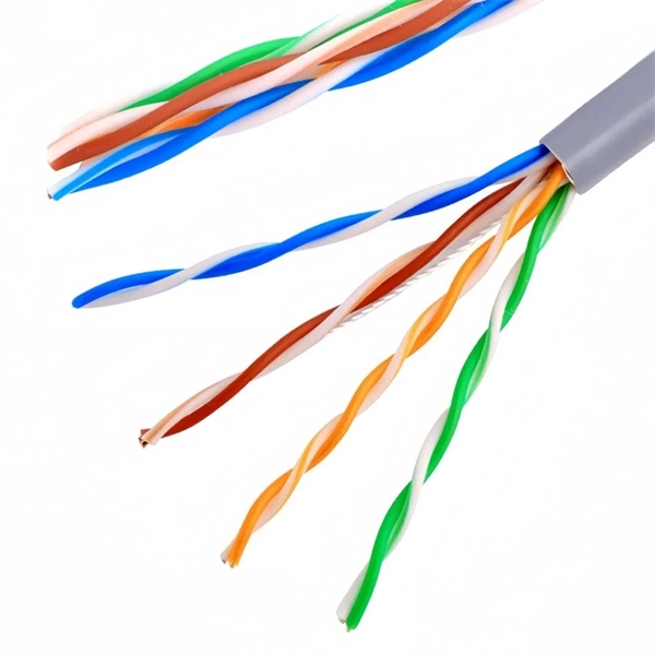
Search results of Top 4 Cabling and Fibre Optics Companies in Madagascar, near me. Listings are verified with accurate business information. Last updated Apr 2026 Unlock the full database with advanced filters and visible emails inside Data Hub — Free Trial available. Electro Standards Laboratories, 3. Zhongshan Meisu Technology Co. What Is a Fiber Switch? What Is a Fiber Switch? A fiber switch is a specialized device for managing optical signals in fiber optic cables. It. Structured cabling is the passive infrastructure that supports the transmission of data, voice, and video signals in a building or campus. It consists of various components, including twisted pair cables, fiber optic cables, and cable accessories. Twisted pair cables are the most common type of. SP Madagascar is a leading procurement, supply and logistics and managed service solutions to industries across Madagascar. Our greatest asset for supply is that we can reach out in-country and internationally to ensure our client base is serviced to the highest standards. We have over 15years of. Post one enquiry and contact the Premium Suppliers and Exporters for Free!. Get Quotes from qualified Suppliers only. Unleash the power of the Internet. Send One enquiry to contact All. Moreover, its Free! - Try Now - Not a Buyer? Want to Sell? Join Now to contact buyers. Our catalog includes 106,450 manufacturers, 20,791 distributors and 94,627 service providers. Our international database.
[PDF]
In this video, we'll guide you through the process of configuring a Huawei Switch for your network. Whether you're setting up a new switch or optimizing your existing network infrastructure, this step-by-step tutorial will help you get the job done efficiently. This document provides campus networks typical configuration examples and feature typical configuration examples. "Campus Networks Typical Configuration Examples" provides typical campus network networking modes and a variety of deployment examples. This document is for switches running V200R003C00 and later. In this video, we'll guide you. Saving Configuration: Save changes to make the configuration permanent: Checking Settings: Use commands like display user-interface console 0 to verify correct configuration. Exiting the Device: Log out of the device after completing the configuration. Enabling Telnet Service and Granting Access on. The Combo interface, also known as the optical-electrical multiplexing interface, consists of two Ethernet ports (one optical and one electrical) on the device panel, and there is only one forwarding interface inside the device.
[PDF]
This diagram highlights media converters, switches, and cable types. Also thanks to Init7 (for the great service), r/FiberOptics and FS for providing me with what I needed to get this setup going. If you find this article useful and you are considering Init7 as your provider you can use my referral code “20700408098” to get CHF 111. - off hardware and also support me. Keeping this page as a placeholder for now. Have any questions? Talk with us directly using LiveChat. A fiber optics network diagram illustrates how high-speed data travels from an internet service provider to end users. By using light signals, fiber optics provide faster speeds and better reliability than. MS Visio has long been the default choice for drafting fiber network diagrams, and with the right stencil libraries it can be used to draw everything from backbone routes to detailed patch panel layouts. When fiber techs look for visio fiber stencils, they are usually solving a very practical. Be among the first to receive important product updates, insights and news. Fiber optic cable is used for everything from demarcation point wiring to network signal distribution to video signal extension. Often, fiber enters the structure to a centralized rack or data room where it is connected to a modem. The modem connects to a network switch which connects each remote.
[PDF]
Most modern fiber-enabled network switches require an SFP transceiver module featuring a duplex (two strand) multimode OM3 or duplex single mode OS2 connection with LC connectors. Direct attach cables with pre-terminated SFP connections may also be used. Download the Application. CONFIGURING THE SWITCH IN DESIGO CC/CERBERUS DMS. CYBERSECURITY DISCLAIMER. 44. This tutorial will explain the steps required to configure fiber optics on a Cisco switch and ensure proper connectivity in your network. This chapter includes the following sections: •Information About Fibre Channel Interfaces, page 1-1 •Configuring Fibre Channel Interfaces, page 1-8 •Configuring Global Attributes for. : 192. 0 De livery of solutions fulfilling the Customers' multitude o. This document is intended to serve as a guide for architecting and deploying fiber optic networks in a customer environment. This installation planning guide describes some basic fundamentals of fiber optic technology, considerations for deployment, and basic testing and troubleshooting procedures. Fiber optic cabling is increasingly used to connect network switches and other datacom equipment, especially in long-distance and mission-critical applications. Fiber provides: Increased internet signal bandwidth.
[PDF]
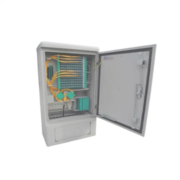
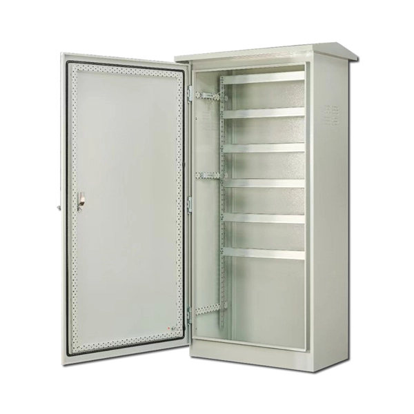
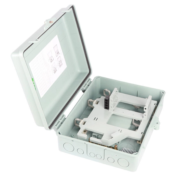
In network cabling, outdoor connections generally use fiber optic cables. When these optical fibers are installed or laid out, a Fiber Termination Box, or FTB, is used to distribute and protect the optical fiber link.
[PDF]
This wikiHow article will teach you how to splice a cut fiber optic cable back together with a fiber optic stripper and cutter and a fiber optic crimper. Trim off any frayed or damaged ends of the cable. Fiber optic cable splicing is the process of joining two fibers end-to-end to create a continuous optical path. In PON and FTTx networks (e., FTTH, FTTP, FTTM), splicing is essential for extending cables, repairing breaks, or connecting backbone and distribution lines. But what happens when you need to join two cables to extend a network or repair a break? You can't just twist them together. This is where fiber optic cable splicing—the. Fiber optic cables are critical components of modern communication networks, transmitting vast amounts of data at lightning speeds. However, physical damage can disrupt this infrastructure and cause significant network issues. When fiber cables sustain damage, specialized repair techniques help. Learn how to splice fiber optic cable step by step in this complete guide! In this video, you'll see the full fiber splicing process — from fiber preparation, cleaving, and fusion splicing to final testing. What is Fiber Optic Splicing and Why is it Needed? – #1. Use and Maintain Your. Whether repairing a broken cable or extending a fiber run, fiber optic splicing ensures light signals travel uninterrupted across vast distances or tight spaces.
[PDF]
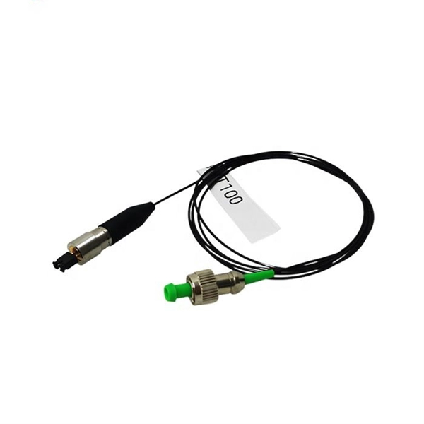
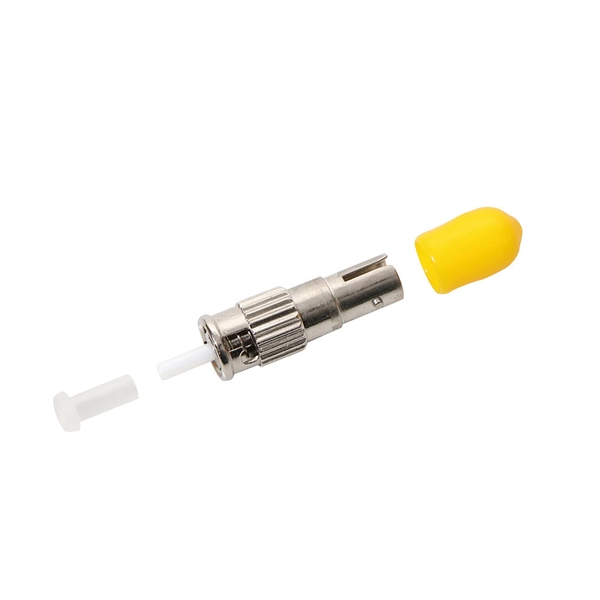
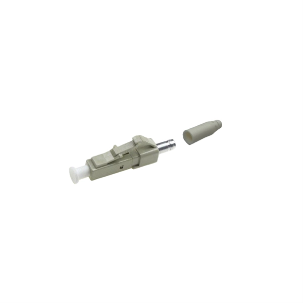
According to different types of pigtail cable connector terminated at the end, there are LC fiber pigtail, SC pigtail, ST pigtail, FC pigtail, fiber pigtail and so on. With different structures and appearance, each of them has their own advantages in diffe. According to different types of pigtail cable connector terminated at the end, there are LC fiber pigtail, SC pigtail, ST pigtail, FC pigtail, fiber pigtail and so on. With different structures and appearance, each of them has their own advantages in different applications and systems. Let's go through some widely used ones. SC Pigtail: SC pigtail. Fiber Optic Pigtails, In fiber optic cable installation, how cables are attached to the system is vital to the success of network. If done properly, optical signals would pass through the link with low attenuation and little return loss. pigtail offers an optimal way to joint optical fiber, which is used in 99% of single-mode applications. This pos. pigtails can be divided into single-mode (colored yellow) and multimode (colored orange) fiber. Multimode pigtails use 62.5/125 micron or 50/125 micron bulk multimode fiber cables and terminated them with multimode fiber optic connectors at one end. 10G multimode fiber cables (OM3 or OM4) are also available in optic pigtails. The jacket color of 10.
[PDF]
This article provides a detailed exploration of Fiber Amplifiers—what they are with regards to Fiber Cabling, how they function, their types, and their significance. Probably the most important application of fiber amplifiers is in optical fiber communications, i., data transmission through optical fibers., every 50 km of fiber. Based on their location and function within the fiber optic line, they are generally categorized as relay amplifiers, preamplifiers, and power amplif. more How to use a fiber. This article explains what optical amplifiers are, how optical amplifiers work, their main types, and why optical amplifiers are indispensable in modern fiber networks. What Is an Optical Amplifier? An optical amplifier is a device that increases the intensity of a light signal traveling through an. High Power Fiber Amplifiers (HPFAs) are critical components in modern optical systems, designed to boost weak optical signals into high-power outputs. Whether you're building long-distance communication links or powering high-intensity laser applications, HPFAs offer the performance, stability, and. Amplification can take place in two ways: the optical signal can be detected, converted to an electrical signal, then returned to the optical domain by modulating an optical source, or an amplifier that directly amplifies the optical signal can be used. The fiber is doped with rare earth elements, such as.
[PDF]
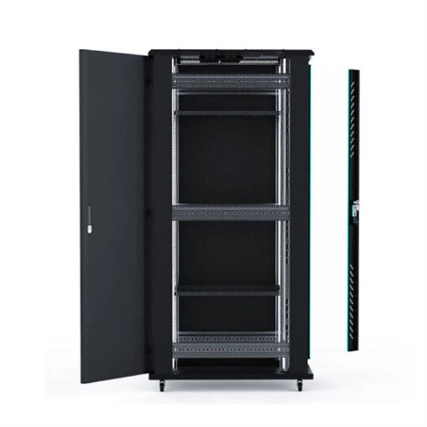
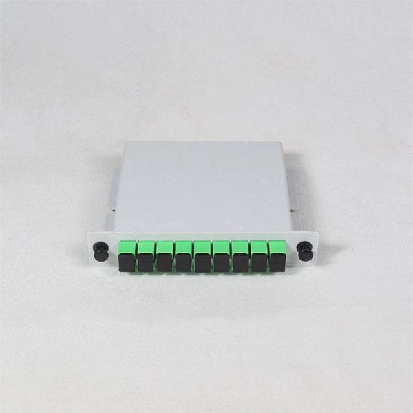
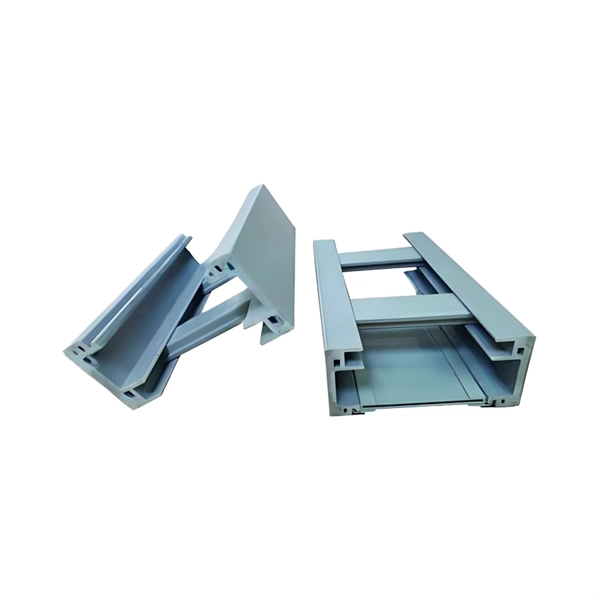
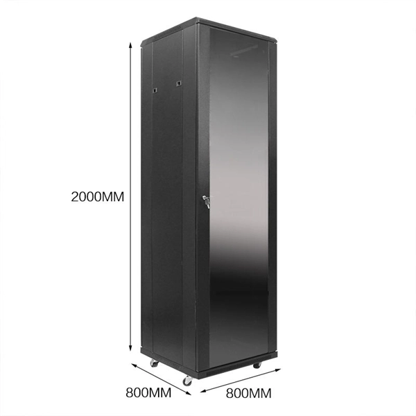
The panel can be pre-loaded completely with the required adapters or pre-loaded with pigtails and splice accessories. The tray is locked by 2 plastic latches and lowers to a 45 degree angle when fully extended. Installation and labeling are simple and easy. FS offers FHD® FAPs and FHU® 1U fibre patch panel with LC, SC, MTP®/MPO connectors in singlemode/multimode fibre to deploy medium for high-density fibre optic network applications. A patch panel or fibre distribution panel is a metal frame with pre- punched holes equally spaced horizontally along the front face. Unpopulated patch panels can be configured with bulkhead. A carefully selected range of fibre optic termination and patch panels from leading brands including Panduit, Canford and Speedway. A handy tool to for quickly finding a populated fibre connection panel that meets your requirements. Rack mounted fibre patch panels create a convenient, professional and easy access way to organise your fibre cables into a cabinet. Latest Optical Fibre Patch Panels for fibre installations.
[PDF]
Converting multimode fiber to single-mode fiber can improve network performance and future-proof infrastructure. This guide will walk you through the methods, challenges, and best practices for successfully converting multimode to . This guide will break down the professional methods to achieve seamless single-mode to multi-mode conversion, ensuring your network integrity and performance. 📝 Why Can't You Directly Connect SMF and MMF? At its heart, the incompatibility is physical. The core size of multi-mode fiber is. How can we convert the multimode to a singlemode fiber system? This complete guide will provide answers to these questions. Mode conversion is typically required when: FlexPoint unmanaged Fiber-to-Fiber Media Converters provide multimode to single-mode conversion, and support a variety of network. Fiber mode conversion, especially multimode to single-mode fiber conversion (MMF-to-SMF conversion) is required when the distance is an important parameter to consider in optical applications. In this tutorial, three methods will be introduced to support mode conversion from multimode to. Multimode fiber (MMF) and single-mode fiber (SMF) are two types of fiber optic cables utilized for transmitting light signals over extended distances (For details, please refer to the blog post “ Choosing the Right Fiber Optic Cable: Singlemode vs Multimode “). The primary distinction between them.
[PDF]
Find and discover Fiber Optic manufacturers and suppliers for all products in Laos, featuring details on their shipment activities, trade volumes, trading partners, and more. View all fiber optic buyers based on products in Laos. Subscribe to global trade data intelligence to discover new business. WWCC is upgrading the products operations through research, advanced technology and machinery, to serve the expanding needs of Laos's economy at competitive prices. The company is committed to offer high quality products to achieve customers' satisfaction. Our fiber optic cables are designed for use in laser surgery, endoscopy, photodynamic therapy, and diagnostic imaging, ensuring superior light transmission. How does 6W market outlook report help businesses in making decisions? 6W monitors the market across 60+ countries Globally, publishing an annual market outlook report that analyses trends, key drivers, Size, Volume, Revenue, opportunities, and market segments. Our insights help.
[PDF]
Fiber internet can deliver lightning-fast speeds, and a capable router is needed to take full advantage of that. That said, we recommend giving the NETGEAR Nighthawk RS700S a shot, as it supports the Wi.
[PDF]
Even when splicing identical fibers together, if they are not perfectly aligned, optical power will be lost and attenuation across the splice will exist. The performance of a fiber optic splice is determined by a number of factors, including the quality of the fiber, the cleanliness of the splice, and the techniques used to make the splice. Intrinsic factors, such as the refractive index of the fiber, are those that are inherent to the fiber itself. Fiber optic cable splicing is the process of joining two fibers end-to-end to create a continuous optical path. In PON and FTTx networks (e., FTTH, FTTP, FTTM), splicing is essential for extending cables, repairing breaks, or connecting backbone and distribution lines. To protect these vulnerable. Fiber loss, also called fiber optic attenuation or attenuation loss, refers to the loss of signal between input and output. Losses can be introduced by various means such as intrinsic material absorption, scattering, bending, connector loss and more. The absorption is caused by the absorption of the light and conversion to heat by molecules in the glass. Primary absorbers are residual OH+ and dopants used to modify the refractive index of the glass. Unlike using connectors, which are designed for frequent connection and disconnection at patch panels, splicing creates a permanent, stable joint with minimal light loss. This process is fundamental to building and.
[PDF]
Fiber splice closures are not used occasionally — they are deployed extensively across every fiber network. The exact quantity depends on population density, network topology, and regional infrastructure planning. There are hundreds of different designs and options on splice closures. Some are designed for concatenation of long distance cables where two identical cables are spliced together. Its role is not only to enclose the splice, but to ensure that optical performance remains stable throughout years of operation. In FTTX and outdoor access networks especially, the reliability of. There are several types of fiber optic splice closures available in the market, each designed for specific applications and environments. There are many possible ways to put two or more cables together or drop a single fiber at a location. It creates an air-tight environment that safeguards these splices from environmental considerations, including wetness, dust, and temperature changes; hence, the. CommScope addresses these challenges with a comprehensive family of fiber splice closures that prioritize essential criteria: reliability, installability, flexibility, and speed of deployment. Trunk and Feeder Network Solutions: These closures are designed for robust performance in the backbone of.
[PDF]