This video shows real on-site footage of electrical installation, demonstrating safe and standardized wiring methods used by professionals. more Learn how to wire a distribution box step by step!. A distribution box, also known as an electrical distribution board, is a critical component in electrical systems. It serves as a central point for distributing electricity to various circuits in a building or facility. It has three categories: residential, commercial and industrial electrical distribution boxes, all of which play important roles in their respective electrical. In modern electrical systems, cable distribution boxes (also known as electrical distribution boxes or distribution boxes) play a crucial role as the key hub for managing, distributing, and protecting circuits. What is the role of the electrical panel? It's also called the breaker box or distribution board. It's the central hub that divides main service lines into smaller branch.
[PDF]
The primary function of a feeder wire is to facilitate bulk power transfer from a central source to a subpanel or a secondary distribution center. An example is the large cable running from the main service panel to a subpanel in a detached garage, basement, or workshop. A main panel and a sub-panel are both important components of an electrical distribution system. It is usually located where the main electrical service enters the building, often on an. Main feeder wires are the arteries of a building's electrical system, designed to safely and efficiently transport a large volume of power from the service entrance to secondary distribution points. They form the backbone of the electrical distribution network, handling the substantial current. An electrical sub panel, also known as a sub distribution board or sub circuit breaker panel, is a smaller secondary panel connected to the main electrical panel in a building. It serves as an extension of the main electrical panel to distribute power to different areas or circuits within a. Distribution board is a safe system designed for house or building that included protective devices, isolator switches, circuit breaker and fuses to safely connect the cables and wires to the sub circuits and final sub circuits including their associated Live (Phase) Neutral and Earth conductors. The distribution box acts as the center of power distribution, distributing electricity to all connected devices.
[PDF]
29 mm 2 (6 AWG, equals 1. 4 mOhm/m) wire is used. This will ensure proper grounding in all applications, independently of tool cable length and number of spindles. Example 1: One spindle with 60 m tool cable: R TOOL CABLE < 3 mOhm x 60 m = 180 mOhm R GND WIRE < 1. 4. In the US a 13. 4. The National Electrical Code (NEC) provides clear guidelines for ground wire sizing through Table 250. 122, but understanding how to apply these requirements correctly can make the difference between a safe installation and a costly code violation. Proper grounding conductor sizing is critical for. Whether you're a seasoned pro or just starting out, this comprehensive guide will give you practical insights into proper grounding techniques, with a special focus on how selecting quality materials from a reliable building material supplier impacts your entire system's safety and longevity. The NEC distinguishes between several types of grounding conductors, each with different sizing. In the US a 13. 66 titled 'Grounding Electrode Conductor For Alternativing Current Systems'. Since. IPMENT, STRUCTURES, ETC. IN ELECTRICAL STATIONS INCLUDING TRANSMISSION AND DISTRIBUTION SUBSTAT GR THAN 8 FT FROM THE FENCE. THE FENCE SHALL BE GROUNDED SEPARATELY FROM THE GRID UNLESS OTHERWISE NOTED ON THE A PROPRIATE PROJECT DRAWING. FOR FENC G O OUTSIDE CLEARANCE SPACING. SEE APPLICATION.
[PDF]
This video shows real on-site footage of electrical installation, demonstrating safe and standardized wiring methods used by professionals. more Learn how to wire a distribution box step by step! This video shows real on-site footage of. Hey, in this article we are going to see the Single Phase Distribution Box Wiring Diagram and Connection Procedure. A distribution board or distribution box is where the main power supply is distributed to multiple loads. And all the switching and protective devices are installed in the. Box installation: Make sure that Distribution box has been correctly installed and fixed. Material preparation: Prepare the required circuit breakers, wires, wiring ties and other materials, and ensure that they meet the design drawings and installation requirements. Location determination:. In this video, we'll walk you through the process of wiring a home distribution box with a detailed connection diagram. Whether you're an electrician or a DIY enthusiast, this guide will help you understand the basics of home electrical distribution. What Is a Distribution Box? A distribution box, also known as an electrical distribution board, is a critical component in electrical systems. It serves as a.
[PDF]
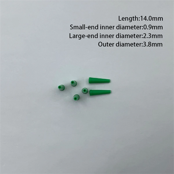
Glass fiber and plastic fiber is fragile. When individual fibers break, light transmission and uniformity are reduced. After the first few fibers break at a stress point, a chain reaction occurs, hastening t.
[PDF]
Classes 1, 2, 3, and 4, communications, fire alarm, and optical fiber cables are all addressed in the NEC. Several changes related to communications cables have received the green light to be included in the 2023 National Electrical Code. Nuclear Regulatory Commission (NRC) is issuing for public comment a draft Regulatory Guide (DG), DG-1427, “Qualification of Fiber-Optic Cables, Connections, and Optical Fiber Splices for Use in Safety Systems for Production and Utilization Facilities. ” DG-1427 is newly proposed Revision 0. The following links on this page are to Adobe Portable Document Format (PDF) files. To obtain a free viewer for displaying this format, see our Plugins, Viewers, and Other Tools. ms for Production and Utilization Facilities. By Stanley Kaufman, PhD, CableSafe Inc. and Ronald Tellas. This part provides guidance to Federal agencies on the implementation of the Buy America Preference applicable to Federal financial assistance set forth in part I of subtitle A, Buy America Sourcing Preferences, of the Build America, Buy America Act included in the Infrastructure Investment and.
[PDF]
This video shows real on-site footage of electrical installation, demonstrating safe and standardized wiring methods used by professionals. A distribution board, also known as a DB box, is like the central hub of an electrical system. It contains multiple circuit breakers and connects various electrical circuits to ensure. Box installation: Make sure that Distribution box has been correctly installed and fixed. Material preparation: Prepare the required circuit breakers, wires, wiring ties and other materials, and ensure that they meet the design drawings and installation requirements. It serves as a central hub for distributing electricity throughout a building, ensuring that power is delivered safely and efficiently to all the required locations. It takes the incoming power and safely distributes it to different circuits throughout your building. Whether in a home or an industrial facility, this box keeps your electrical setup organized, functional, and efficient. It has three categories: residential, commercial and industrial electrical distribution boxes, all of which play important roles in their respective electrical.
[PDF]
This document is intended for network engineers responsible for switch configuration and management. You should be familiar with basic Ethernet knowledge and have extensive experience in network deployment and management. The symbols that may be found in this document are defined. S7700&S8700&S9700&S12700&S16700 Series: Access product manuals, HedEx documents, product images and visio stencils. Symbol Description Indicates a potentially hazardous situation which, if not avoided, could result in equipment damage, data loss, performance deterioration, or unanticipated results. NOTICE is used to address practices not related to personal injury. Supplements the important information in the. Page 1 Quidway S7700 Smart Routing Switch V100R006C00 Configuration Guide - SPU Issue Date 2011-07-15 HUAWEI TECHNOLOGIES CO. Page 2 All other trademarks and trade names mentioned in this document are the property of their respective holders. Notice The purchased products, services and. line starting with the # sign is comments. In device configuration, use the existing interface numbers on devices. To ensure device security, use ciphertext when configuring a password and change the password periodically.
[PDF]
Practice good wiring: secure grounding, neat cable management, proper insulation, and correct wire gauge and breaker size. Include protection devices like breakers, fuses, and surge protectors—each circuit should have its own protection. Comply with standards: Follow NEC, IEC . We'll show you how to run the wires, install the proper jacks and hook up the central distribution box. The new system doesn't mean you have to scrap your old cables and jacks. Existing phone lines and jacks can coexist with your new communication wiring system. We recommend that you initially. Learn how to wire a distribution box step by step! This video shows real on-site footage of electrical installation, demonstrating safe and standardized wiring methods used by professionals. And all the switching and protective devices are installed in the distribution box. Single Phase Distribution Box generally consists of Double Pole MCBs, Single Pole MCBs, and RCCBs. It is usually equipped with circuit breakers, fuses, terminal connectors, and other components. It is mainly used to isolate fault circuits, prevent overload, and ensure the safe operation of. Material preparation: Prepare the required circuit breakers, wires, wiring ties and other materials, and ensure that they meet the design drawings and installation requirements. Location determination: Determine the installation position of the circuit breaker according to the position of the.
[PDF]
A waxed cord, called lacing cord, is used for binding the conductors. The cord comes in two sizes; #6 is used for small or medium sized cables, #8 is used for larger cables. A shuttle on which the lacing cord can be wound makes it easier to handle the cord. Cable lacing is a method for tying wiring harnesses and cable looms, traditionally used in telecommunication, naval, and aerospace applications. This old cable management technique, taught to generations of lineworkers, is still used in some modern applications since it does not create. BM-Rosendahl is the global supplier of production equipment for lead-acid and lithium-ion batteries. The portfolio ranges from solutions and equipment for enveloping, sleeving, wrapping & stacking, cast-on-strap to the assembly of automotive, motorcycle, industrial, and e-mobility batteries. The invention provides an optical cable cabling and yarn binding method, an optical cable cabling method, an optical cable and communication equipment, and relates to the technical field of optical cable manufacturing. To achieve optimum binding process requires knowledge about both binder and material. This Standard may also apply to the Jet Propulsion Laboratory other contractors, grant recipients, or parties to agreements PR 8735. 2, Hardware Quality Assurance Program Requirements for Programs and Projects.
[PDF]
Where single conductor cables comprising each phase, neutral, or grounded conductor of an alternating-current circuit are connected in parallel as permitted in 310. Joining conductors in parallel is like having two or more smaller conductors connected at each end to make one larger conductor. The single input supply (phase and neutral) is connected to this main MCB. When this MCB is turned on all other MCBs will get the power supply. Single-pole MCBs are used for the output loads. The isolator is used to OPEN and CLOSE the lines manually, which is the main switch of the electrical system. The RCCB is a device used. These are usually connected to thick black or red wires, each carrying 120V in a split-phase system. Verify voltage with a multimeter: each line wire should show ~120V to neutral and ~240V across both hot wires. Load terminals, positioned below the line lugs, distribute current to downstream. What's a neutral?The IEEE defines a Neutral as the conductor that has an equal potential difference between it and all other conductors (hot wires). An example of a neutral wire would be the white/gray wire of a single-phase 120/240 volt system or a three-phase 4-wire Wye system, Figure 1-1. 10 (G) (2) through (G) (6).
[PDF]
Live (L) Wire Connection: In a distribution box setup, the incoming live wire (also known as phase or hot wire, denoted as L or Line) connects to the line terminal of the circuit breaker. This serves as the primary source of electrical energy from the mains supply. Correct wiring methods for circuit breakers within distribution boxes are fundamental to ensuring electrical safety and compliance with established codes. The distinction between 1P and 2P circuit breakers plays a pivotal role in determining the appropriate protection level for various circuits. And all the switching and protective devices are installed in the distribution box. Single Phase Distribution Box generally consists of Double Pole MCBs, Single Pole MCBs, and RCCBs. The wire neutral is the return line in an electrical system that brings current from the electrical equipment back to the transformer or distribution box, completing the loop closure of the current. Figure 2-3 What wire is neutral? What does the neutral wire do? Although the neutral wire is usually. Live wires carry the power from the source to a switch or appliance. These may be light switches, electrical outlets, or junction boxes for light fixtures. The live wire is always under voltage, meaning it carries the. The main service panel, also known as the breaker box, is the central distribution point for the home's electrical system.
[PDF]

Thinner cables can be utilized to connect the control switch to the relay; this saves space, weight, and cost. The same voltage and current ratings as other types of switches, such as mechanical switches, do not limit relays. This handbook covers the code of practice in protection circuitry including standard lead and device numbers, mode of connections at terminal strips, colour codes in multicore cables, dos and donts in execution. Also principles of various protective relays and schemes including special protection. A control relay is an electrically operated switch that enables current to flow through a coil that closes or opens the switch. Relays use a small current to control a larger current, making them ideal for controlling high-power devices such as motors, lights, valves, and sensors. When a relay contact is open, this will switch power ON for a circuit when the coil is activated. You'll connect a low-power control circuit to the relay's coil (terminals 85 and 86), which then flips a switch for a separate, high-power circuit running through the. Electrical protection relay has two type protecton as HT panel protection and LT panel protection. HT panel protection relay. The HT power supply is received from GO switch and distributed to the. The rectangular devices are test connection blocks, used for testing and isolation of instrument transformer circuits. : 4 The first protective relays were electromagnetic.
[PDF]
In this video, we'll walk you through the process of wiring a home distribution box with a detailed connection diagram. Whether you're an electrician or a DIY enthusiast, this guide will help you understand the basics of home electrical distribution. more Welcome to our channel! In this video. Understanding the wiring diagram of an electrical panel box is essential for electricians and homeowners alike, as it allows them to troubleshoot any electrical issues, carry out repairs, or make additions to the system. The electrical panel box wiring diagram provides a visual representation of. A distribution board or distribution box is where the main power supply is distributed to multiple loads. And all the switching and protective devices are installed in the distribution box. Single Phase Distribution Box generally consists of Double Pole MCBs, Single Pole MCBs, and RCCBs. Connect the two hot conductors (typically black and red) to the line terminals of the main disconnect switch. Tighten each lug to 250 inch-pounds using a torque wrench. What is Distribution Board? Distribution board.
[PDF]
In this video, we'll walk you through the process of wiring a home distribution box with a detailed connection diagram. Whether you're an electrician or a DIY enthusiast, this guide will help you understand the basics of home electrical distribution. What is Distribution Board? Distribution board. An electrical panel box, also known as a breaker box or a distribution board, is a crucial component of any electrical system. It serves as a central hub for distributing electricity throughout a building, ensuring that power is delivered safely and efficiently to all the required locations. Distribution Board or DB is an electricity supply system or a common enclosure that distributes the electrical power feed into subcircuits. It includes isolator, RCCB (Residual current circuit breaker) or RCD (Residual-current device) devices, protective fuses or MCB's (Miniature Circuit Breaker). A distribution board or distribution box is where the main power supply is distributed to multiple loads. And all the switching and protective devices are installed in the distribution box. Single Phase Distribution Box generally consists of Double Pole MCBs, Single Pole MCBs, and RCCBs. In the following tutorial, we will show how to wire 120V single-phase and 240V split-phase circuit breakers and loads inside a residential main panel. The figure below shows a typical breaker panel used for 120V and 240V circuits. Three conductors enter the main panel from the energy meter and main.
[PDF]