Multiple traffic channels can be assigned different wavelengths and then multiplexed (mixed) onto a fiber link with WDM filter devices. On the other end of the network, WDM filters will demultiplex (separate) the signals for the respective channels. Wavelength division multiplexing (WDM), known as the classic technology that provides optimal solutions for transporting large amounts of data between sites. With the endless upgrades and improvements, WDM technology is no longer just adopted by carriers and service providers, but also applied for. Wavelength Division Multiplexing (WDM) is a technology that allows network operators to multiply the data-carrying capacity of existing fiber optic lines. Read on to learn the fundamentals of this useful technology. WDM allows communication in both the directions in the fiber cable., colors) of laser light. This technique enables bidirectional communications over a. From cloud services and 5G networks through to streaming and enterprise connectivity, service providers and businesses need faster, more efficient ways to scale their networks.
[PDF]
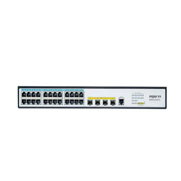
Most modern fiber-enabled network switches require an SFP transceiver module featuring a duplex (two strand) multimode OM3 or duplex single mode OS2 connection with LC connectors. Direct attach cables with pre-terminated SFP connections may also be used. Download the. In this article, we'll explain how to connect multiple Ethernet switches using fiber optic cables and the equipment required for this to work. Network topology refers to the way in which the links and nodes of a network are arranged in relation to each other. Download the Application PDF SFP transceiver. Choose an SFP module based on the fiber optic cabling that will be connected to the network switches. Always integrate duplex (two strand) fiber optic cabling or higher strand counts. So all PCs connected to each switch would reach the LAN/WAN from the other switch. The connection between two or more Ethernet switches in a certain way (Uplink port, etc. ) is called the cascade. Connecting a fiber optic switch involves several steps, ensuring compatibility between the switch's ports and the fiber optic cable. The process requires understanding the type of fiber optic port on your switch and selecting the appropriate transceiver module. Fiber optic switches utilize.
[PDF]
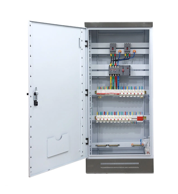
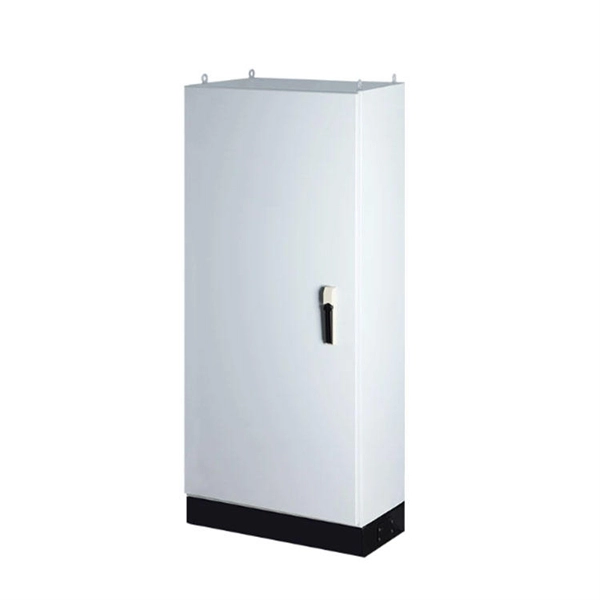
In this video, we'll walk you through the process of wiring a home distribution box with a detailed connection diagram. Whether you're an electrician or a DIY enthusiast, this guide will help you understand the basics of home electrical distribution. more Welcome to our channel! In this video. How to wire a household distribution box? How to pg clamps. When it comes to decoration, many friends like to do it themselves. However, when encountering water and electricity and other links that have a greater impact on the overall decoration, you must do your homework and not implement it. An electrical panel box, also known as a breaker box or a distribution board, is a crucial component of any electrical system. It serves as a central hub for distributing electricity throughout a building, ensuring that power is delivered safely and efficiently to all the required locations. Distribution Board or DB is an electricity supply system or a common enclosure that distributes the electrical power feed into subcircuits. What is Distribution Board? Distribution board. A distribution board or distribution box is where the main power supply is distributed to multiple loads. And all the switching and protective devices are installed in the distribution box. Single Phase Distribution Box generally consists of Double Pole MCBs, Single Pole MCBs, and RCCBs.
[PDF]
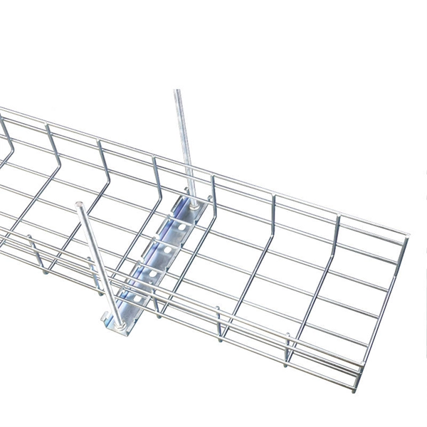
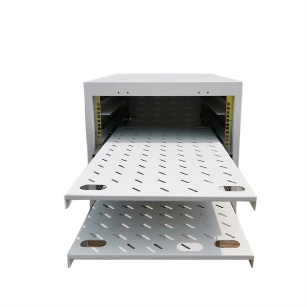
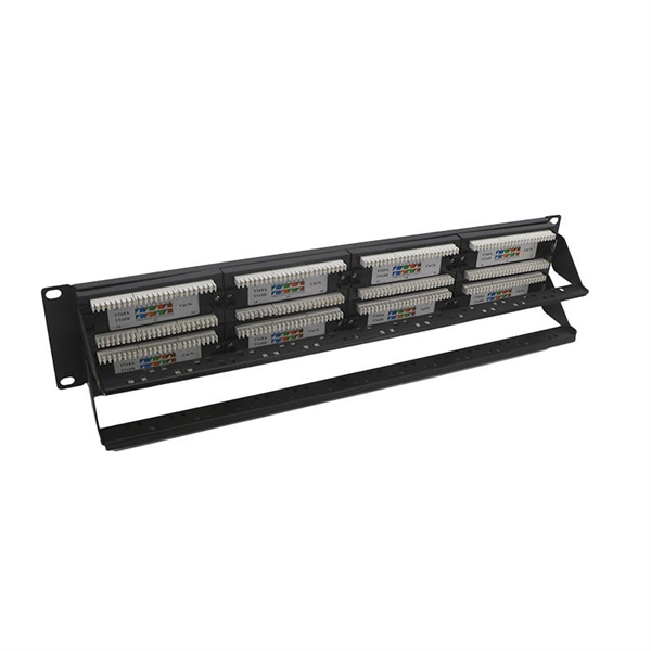
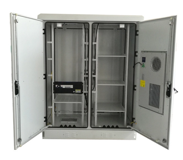
In this video, we take you through the step-by-step installation of Optical Distribution Frames (ODF) and Optical Fiber Patch Panels—key components in setting up a robust fiber optic network. At Eman Communications, we specialize in delivering high-quality installations that ensure opt. more In. Fiber optic patch panels are mostly mounted in 19 inch relay racks, but they can also be mounted on freestanding rails, in cabinets and also on walls. The fiber optical patch panel is convenient for people to easily access the optical fiber cable in the panel. Keeping this page as a placeholder for now. Have any questions? Talk with us directly using LiveChat. An ODF is a centralized platform designed for terminating, cross-connecting, and managing optical fibers. It ensures fiber management is structured, minimizes signal loss, and provides accessibility for maintenance and future expansion. ODF Rack/Cabinet: Physical frame housing all terminations and. To connect fiber optic cables to a patch panel, users must follow a specific procedure that ensures proper connectivity and signal transmission. Here is a step-by-step guide on how to connect fiber optic cables to a patch panel. Step 1: Gather the Tools and Equipment The first step in connecting.
[PDF]
Each wire must connect to its appropriate terminal: Live wires (red or brown) connect to the MCB's live terminal. Neutral wires (black or blue) go to the neutral bus bar. Welcome to our channel! In this video, we'll walk you through the process of wiring a home distribution box with a detailed connection diagram. Whether you're an electrician or a DIY enthusiast, this guide will. This guide provides step-by-step instructions for connecting a distribution box and highlights key factors to consider during installation. What Is a Distribution Box? A distribution box, also known as an electrical distribution board, is a critical component in electrical systems. In Single Phase supply (230V in UK, EU and 120V & 240V in the US & Canada), there are two (one is Line (aka Phase, Hot or Live) and the other one is Neutral) incoming cables from the utility poles to the kWh energy. A distribution board or distribution box is where the main power supply is distributed to multiple loads. And all the switching and protective devices are installed in the distribution box. Single Phase Distribution Box generally consists of Double Pole MCBs, Single Pole MCBs, and RCCBs.
[PDF]
Welcome to our channel! In this video, we'll walk you through the process of wiring a home distribution box with a detailed connection diagram. What Is a Distribution Box? A distribution box, also known as an electrical distribution board, is a critical component in electrical systems. It serves as a. A distribution board or distribution box is where the main power supply is distributed to multiple loads. And all the switching and protective devices are installed in the distribution box. Single Phase Distribution Box generally consists of Double Pole MCBs, Single Pole MCBs, and RCCBs. What is Distribution Board? Distribution board. In this step by step tutorial, we will show how to wire a single Phase Consumer Unit Installation in home from Utility Pole to a Single-Phase Energy Meter & Single-Phase Distribution board and then How to connect Single Phase Loads in single Phase Wiring Distribution System in home electric supply.
[PDF]
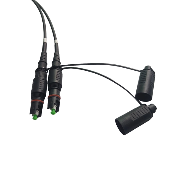
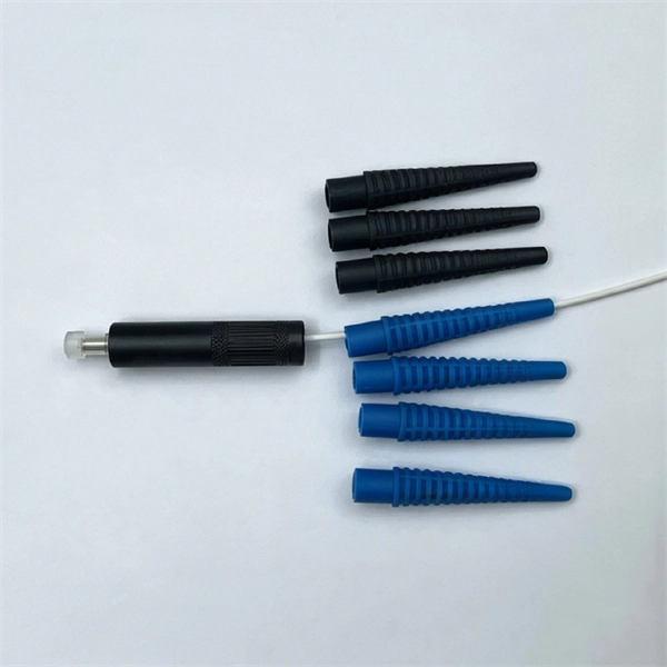
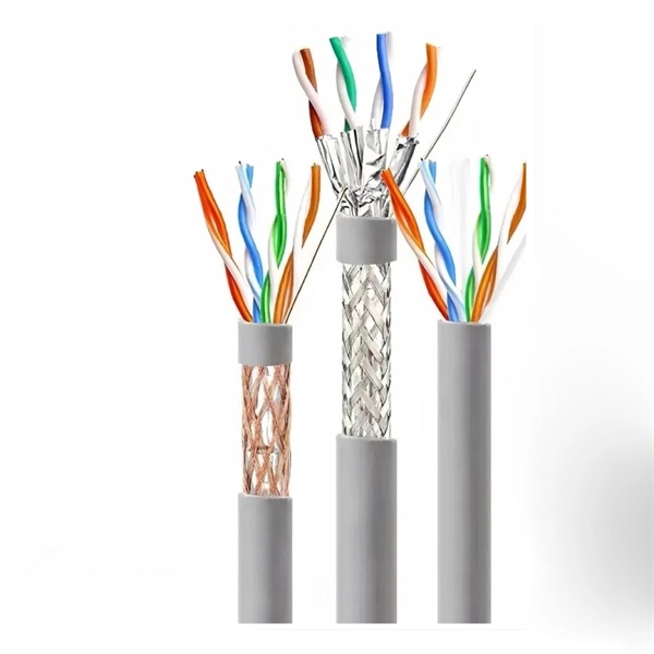
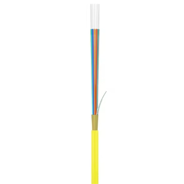
This guide provides a complete installation process for armored fiber optic cords, explaining each step from routing and pulling to stripping, cleaning, and testing. It also highlights key differences from standard fiber cables and important precautions to ensure safety and. This article provides practical guidance on how to install armored fiber cables safely, covering key considerations, step-by-step procedures, and addressing common questions. With proper. ShowMeCables offers a wide range of armored fiber optic cables featuring same-day shipping. These armored fiber cables provide network safety without compromising flexibility or performance. This. The armoured patch cord is engineered for environments where a standard patch cord would be prone to damage. Robust Internal. The armored fiber optic cable is to wrap a layer of protective “armor” on the outside of the optical fiber, which is mainly used to meet the requirements of anti-rodent and moisture resistance. This cable is used within buildings to provide high-density connectivity and ease of installation. Interlocking aluminum armor eliminates the need for inner duct or conduit to provide a smal er crush resistant.
[PDF]
Router Connection: Begin by inserting the fiber cable into the router. When securely connected, the cable should click into place. Testing the Connection: Once connected, test the connection to ensure no immediate. The process to connect fiber optic cable to router requires careful attention to detail, but I'll walk you through every critical step with the precision and clarity you deserve. This comprehensive guide combines industry standards with field-tested practices to ensure you achieve a rock-solid. However, setting up a fiber optic connection to your router can seem daunting if you're unfamiliar with the process. In this guide, we'll walk you through how to connect a fiber optic cable to a router safely and efficiently. Our Experts are helping user's, who are facing issues with their tech gadgets like Router, Modem and extender. The fiber optic cable does not plug directly into a standard home router because the signal type must be translated. Check compatibility: Before you begin, make sure your router supports fiber optic connection.
[PDF]
The hydraulic wrench head and power pack are connected by a 10,000 psi (68,900 kPa) single-line hose assembly. Each end of the hose will have one female connector. When you install a distribution box, you need a variety of tools to get the job done safely and efficiently. A measuring tape and. Never connect or disconnect any hydraulic hoses or fittings without first unloading the wrench and the pump. Open all hydraulic controls several times to make sure the system has been completely depressurized. If the system includes a gauge, double check the gauge to make sure pressure has been. et that came with your hydraulic t lly inspect all components for shipping damage. If ximum Working Pressure is 10,000 PSI (700 bar). We use baier high pressure hoses to connect the torque wrench and hydraulic pump. Some illustrations in this manual may show details or attachments different from your hoist. Some components have been removed for illustrative purposes. Drawings. Overview The Enerpac S-Series hydraulic torque wrench is designed for controlled tightening and loosening of fasteners in industrial bolting applications. The wrench features a removable square drive shaft that is designed to accept a wide variety of interchangeable hex sockets of different sizes.
[PDF]
In this guide, we will walk you through the process of setting up a network switch, from selecting the right equipment to connecting and testing the network. Ethernet switches, also called network switches, connect multiple devices via Ethernet cables. In contrast, a router connects your local area network (LAN) to the internet's. A practical, current guide to planning, pulling and terminating Cat6/Cat6A cable — tools, techniques, testing and labeling for reliable results. By Thomas McCormack • Updated Mar 17, 2026 • 12 min read • Lead Technician and Engineer, Data Wire Solutions Disclosure: Some links may be affiliate. With an Ethernet cable, you can hardwire your devices to your network, providing fast and efficient. Your ethernet switch doesn't come with any ethernet cables, so you want to have some on hand when setting up your switch. You'll need one cable to connect your ethernet switch and router together (assuming you want to provide your devices with an ethernet connection to the internet), and an. A network switch is a crucial component in any modern network, enabling seamless communication between devices. By the end of this tutorial. Connecting a network switch involves physically connecting devices using Ethernet cables and configuring them as needed, ultimately expanding your network connectivity and improving network performance. Connecting a network switch is a foundational skill for anyone managing a home or small business.
[PDF]

Thinner cables can be utilized to connect the control switch to the relay; this saves space, weight, and cost. The same voltage and current ratings as other types of switches, such as mechanical switches, do not limit relays. This handbook covers the code of practice in protection circuitry including standard lead and device numbers, mode of connections at terminal strips, colour codes in multicore cables, dos and donts in execution. Also principles of various protective relays and schemes including special protection. A control relay is an electrically operated switch that enables current to flow through a coil that closes or opens the switch. Relays use a small current to control a larger current, making them ideal for controlling high-power devices such as motors, lights, valves, and sensors. When a relay contact is open, this will switch power ON for a circuit when the coil is activated. You'll connect a low-power control circuit to the relay's coil (terminals 85 and 86), which then flips a switch for a separate, high-power circuit running through the. Electrical protection relay has two type protecton as HT panel protection and LT panel protection. HT panel protection relay. The HT power supply is received from GO switch and distributed to the. The rectangular devices are test connection blocks, used for testing and isolation of instrument transformer circuits. : 4 The first protective relays were electromagnetic.
[PDF]
Connect the fiber optic cable: Attach the fiber optic cable's connector to the transceiver module on the switch. Make sure the connector type (e., SC, LC) matches the transceiver module. Fiber optic cabling is increasingly used to connect network switches and other datacom equipment, especially in long-distance and mission-critical applications. Fiber provides: Increased internet signal bandwidth. Most modern fiber-enabled network switches require an SFP transceiver module. A newly added feature on some Microchip Gigabit Ethernet switches is a serial Gigabit media independent interface (SGMII) for one of the ports. This is a low pin count interface for connecting the switch to a Gigabit Ethernet PHY, to a fiber optic transceiver, or to another switch. The following. This document describes how to troubleshoot fiber optic interfaces by addressing some of the fiber optic module and cabling specifications. There are no specific requirements for this document. The information in this document is based on all Catalyst 9000 Series switches. This includes Doppler. Multimode fiber optic switches have emerged as a crucial component, enabling seamless connectivity and efficient data transmission. This is a cost-effective and high performance way to connect network switches. Advantages Determine the length of the fiber run and choose either multi mode for runs under 1000 feet or single mode for runs over 1000 feet. Fiber optic switches utilize.
[PDF]
Trim solid or stranded wire to length and insert into clamp-style terminals. Tighten with a screwdriver. Tug on all connections to make sure they are secure. Close up electrical boxes. Turn on the power and check your work. Learn how to wire a distribution box step by step! This video shows real on-site footage of electrical installation, demonstrating safe and standardized wiring methods used by professionals. Make sure the power's off using a non-contact voltage tester or multimeter. One final tip: Get into the habit of making connections in this. This guide provides step-by-step instructions for connecting a distribution box and highlights key factors to consider during installation. What Is a Distribution Box? A distribution box, also known as an electrical distribution board, is a critical component in electrical systems. It serves as a. Material preparation: Prepare the required circuit breakers, wires, wiring ties and other materials, and ensure that they meet the design drawings and installation requirements. Choose the right box based on environment (indoor/outdoor), load capacity, and durability. Check for proper IP/NEMA ratings and material quality. Beginning of dialog window. Escape will cancel and close the window. This modal can be closed by pressing the Escape key or activating the close button.
[PDF]
In this step by step tutorial, we will be showing the portable generator wiring and connection diagram to the home supply and main distribution board according to NEC and IEC. These portable power distribution units allow you to safely and reliably bring power into work zones, especially when running tools and equipment in areas without finished electrical infrastructure. In this weekly how-to, powered by KnowHow, we'll walk you through how to safely set up, test, and. To safely and efficiently distribute power from a portable generator, a portable generator connection box is an essential accessory. We will be using Automatic Changeover Switch also known as Automatic Transfer Switch (ATS), Manual Changeover Switch (MTS. A crucial way to keep your house up and running during an outage is install a transfer switch and connect it to a portable power station. This post will walk you through the installation of a transfer switch and how to integrate it with your portable power station so you can stay prepared and keep. Learn how to wire a distribution box step by step! This video shows real on-site footage of electrical installation, demonstrating safe and standardized wiring methods used by professionals. 6 Earthing of power distribution box (optional) position, or to the green display (2) (dependent on the protective element). Close the inspection window. 7 Power distribution box.
[PDF]
In this instructional video, Test Equipment Product Manager, Bob Licari demonstrates how to use a Miller Round Cable Slitter MK02. This tool allows you to remove the outer tube from your fiber optic cable without damaging the fibers. more. A Fiber Cable Slitter is an indispensable tool for any technician working with fiber optic networks. In fact, its importance cannot be overstated when it comes to preparing cables for splicing or termination. When these vital communication arteries need to be joined together, fusion splicing machines come to the rescue. The key to a successful splice is preparation, precision, and the right equipment. A fusion splicer uses heat to fuse the glass cores of two fibre optic cables, creating a seamless connection with. In this guide, we cover the basics of fiber optic splicing, how to perform splicing using two different methods, and finally some best practices to perform good fiber splicing. What is Fiber Optic Splicing and Why is it Needed? – #1. Use and Maintain Your. The operation and skills of fiber optic fusion splicing technology can be mainly divided into five steps: fiber stripping, fiber cutting, fiber melting, fiber sleeve, and fiber winding. And tools used for fiber fusion: fusion splicer; fiber cleaver; cable stripper; fiber optic stripper; alcohol;.
[PDF]