In this video, we'll walk you through the process of wiring a home distribution box with a detailed connection diagram. Whether you're an electrician or a DIY enthusiast, this guide will help you understand the basics of home electrical distribution. more Welcome to our channel! In this video. A distribution board or distribution box is where the main power supply is distributed to multiple loads. And all the switching and protective devices are installed in the distribution box. Single Phase Distribution Box generally consists of Double Pole MCBs, Single Pole MCBs, and RCCBs. Single Phase wiring installation is the most common wiring in residential buildings. It is essential for managing the electrical supply to various appliances and circuits in the building. Its function is to safely divide the incoming high-amperage utility power into smaller, manageable branch circuits that supply power to lights, outlets, and.
[PDF]
This video shows real on-site footage of electrical installation, demonstrating safe and standardized wiring methods used by professionals. more Learn how to wire a distribution box step by step! This video shows real on-site footage of. A ddc panel wiring diagram provides a visual representation of the connections and wiring between the ddc panel and other components in the building automation system. It includes information about the various input and output points, the power supply, and the communication channels. A. A distribution box is the heart of any electrical system. It takes the incoming power and safely distributes it to different circuits throughout your building. Whether in a home or an industrial facility, this box keeps your electrical setup organized, functional, and efficient. This section will explain its function, types, and the importance of correct. A facility's direct digital controls (DDCs) form a living, breathing system that an owner will use throughout the life of the building. However, many control systems do not work as designed on “Day One,” much less after two to three years of use. Adding to the complexity are subcontractors, who. Strictly speaking, the word “Distribution Box (D-box)” can refer to two categories: electrical distribution boxes and septic tank distribution boxes. This article mainly talks about the first one. An electrical distribution box, also known as a power distribution box, panelboard, or consumer unit.
[PDF]
In this video, we'll walk you through the process of wiring a home distribution box with a detailed connection diagram. Whether you're an electrician or a DIY enthusiast, this guide will help you understand the basics of home electrical distribution. more Welcome to our channel! In this video. Understanding the wiring diagram of an electrical panel box is essential for electricians and homeowners alike, as it allows them to troubleshoot any electrical issues, carry out repairs, or make additions to the system. The electrical panel box wiring diagram provides a visual representation of. A distribution board or distribution box is where the main power supply is distributed to multiple loads. And all the switching and protective devices are installed in the distribution box. Single Phase Distribution Box generally consists of Double Pole MCBs, Single Pole MCBs, and RCCBs. Connect the two hot conductors (typically black and red) to the line terminals of the main disconnect switch. Tighten each lug to 250 inch-pounds using a torque wrench. What is Distribution Board? Distribution board.
[PDF]
This video shows real on-site footage of electrical installation, demonstrating safe and standardized wiring methods used by professionals. more Learn how to wire a distribution box step by step!. A distribution box, also known as an electrical distribution board, is a critical component in electrical systems. It serves as a central point for distributing electricity to various circuits in a building or facility. It has three categories: residential, commercial and industrial electrical distribution boxes, all of which play important roles in their respective electrical. In modern electrical systems, cable distribution boxes (also known as electrical distribution boxes or distribution boxes) play a crucial role as the key hub for managing, distributing, and protecting circuits. What is the role of the electrical panel? It's also called the breaker box or distribution board. It's the central hub that divides main service lines into smaller branch.
[PDF]
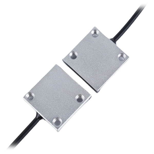
On the US market, a 5. 26 mm 2 (10 AWG) ground wire must be used, and in all other markets a 6 mm 2 must be used. Grounding of the units: Attach a ground wire from one of the threaded studs (A) at the bottom of the housing, to the mounting plate (B). Attach a second grounding wire from the mounting. The correct connection method of Distribution box grounding wire mainly includes the following steps: 1. Find the grounding bar or PE bar Open the distribution box and find the position marked with the grounding plate or PE letter. The basic rule achieves this through an equipment grounding jumper; four exceptions. An equipment grounding conductor passing through the box without a splice is not required to be joined inside the box to others that are spliced in the box. 148 addresses the continuity of equipment grounding conductors and their attachment in boxes. Not all boxes are metal or provide. Correct grounding of services depends upon understanding the definition and role of the grounded conductor. The neutral conductor is typically the grounded conductor connected to the system's neutral point, carrying current under normal operation. Whether you're a seasoned pro or just starting out, this comprehensive guide will give you practical.
[PDF]
This video shows real on-site footage of electrical installation, demonstrating safe and standardized wiring methods used by professionals. A distribution board, also known as a DB box, is like the central hub of an electrical system. It contains multiple circuit breakers and connects various electrical circuits to ensure. Box installation: Make sure that Distribution box has been correctly installed and fixed. Material preparation: Prepare the required circuit breakers, wires, wiring ties and other materials, and ensure that they meet the design drawings and installation requirements. It serves as a central hub for distributing electricity throughout a building, ensuring that power is delivered safely and efficiently to all the required locations. It takes the incoming power and safely distributes it to different circuits throughout your building. Whether in a home or an industrial facility, this box keeps your electrical setup organized, functional, and efficient. It has three categories: residential, commercial and industrial electrical distribution boxes, all of which play important roles in their respective electrical.
[PDF]
In this video, we'll walk you through the process of wiring a home distribution box with a detailed connection diagram. Whether you're an electrician or a DIY enthusiast, this guide will help you understand the basics of home electrical distribution. What is Distribution Board? Distribution board. An electrical panel box, also known as a breaker box or a distribution board, is a crucial component of any electrical system. It serves as a central hub for distributing electricity throughout a building, ensuring that power is delivered safely and efficiently to all the required locations. Distribution Board or DB is an electricity supply system or a common enclosure that distributes the electrical power feed into subcircuits. It includes isolator, RCCB (Residual current circuit breaker) or RCD (Residual-current device) devices, protective fuses or MCB's (Miniature Circuit Breaker). A distribution board or distribution box is where the main power supply is distributed to multiple loads. And all the switching and protective devices are installed in the distribution box. Single Phase Distribution Box generally consists of Double Pole MCBs, Single Pole MCBs, and RCCBs. In the following tutorial, we will show how to wire 120V single-phase and 240V split-phase circuit breakers and loads inside a residential main panel. The figure below shows a typical breaker panel used for 120V and 240V circuits. Three conductors enter the main panel from the energy meter and main.
[PDF]
In this video, we'll walk you through the process of wiring a home distribution box with a detailed connection diagram. Whether you're an electrician or a DIY enthusiast, this guide will help you understand the basics of home electrical distribution. more Welcome to our channel! In this video. A distribution box is the heart of any electrical system. It takes the incoming power and safely distributes it to different circuits throughout your building. However, the key to. In this article, we'll explain how to install a weatherproof electrical box, from selecting the right materials to properly securing the box in place. Weatherproof electrical boxes are designed to handle extreme weather conditions, such as heavy rain and strong winds. They're also designed to. Whether you're a do-it-yourselfer, the neighborhood handyman, or a professional electrician, knowing how to properly install a weatherproof electrical junction box can save time, and your system components will continueto operate for years. Standard indoor electrical boxes are not designed to handle exposure to rain, snow, or high humidity, which can quickly lead to corrosion. Whether adding a GFCI outlet for safety or upgrading an exterior outlet for weather-resistant durability, it's essential to follow proper electrical wiring guidelines to ensure compliance with local codes and prevent hazards. This guide explains the different types of outdoor electrical boxes.
[PDF]
This video shows real on-site footage of electrical installation, demonstrating safe and standardized wiring methods used by professionals. more Learn how to wire a distribution box step by step! This video shows real on-site footage of. Hey, in this article we are going to see the Single Phase Distribution Box Wiring Diagram and Connection Procedure. A distribution board or distribution box is where the main power supply is distributed to multiple loads. And all the switching and protective devices are installed in the. Box installation: Make sure that Distribution box has been correctly installed and fixed. Material preparation: Prepare the required circuit breakers, wires, wiring ties and other materials, and ensure that they meet the design drawings and installation requirements. Location determination:. In this video, we'll walk you through the process of wiring a home distribution box with a detailed connection diagram. Whether you're an electrician or a DIY enthusiast, this guide will help you understand the basics of home electrical distribution. What Is a Distribution Box? A distribution box, also known as an electrical distribution board, is a critical component in electrical systems. It serves as a.
[PDF]
Practice good wiring: secure grounding, neat cable management, proper insulation, and correct wire gauge and breaker size. Include protection devices like breakers, fuses, and surge protectors—each circuit should have its own protection. Comply with standards: Follow NEC, IEC . We'll show you how to run the wires, install the proper jacks and hook up the central distribution box. The new system doesn't mean you have to scrap your old cables and jacks. Existing phone lines and jacks can coexist with your new communication wiring system. We recommend that you initially. Learn how to wire a distribution box step by step! This video shows real on-site footage of electrical installation, demonstrating safe and standardized wiring methods used by professionals. And all the switching and protective devices are installed in the distribution box. Single Phase Distribution Box generally consists of Double Pole MCBs, Single Pole MCBs, and RCCBs. It is usually equipped with circuit breakers, fuses, terminal connectors, and other components. It is mainly used to isolate fault circuits, prevent overload, and ensure the safe operation of. Material preparation: Prepare the required circuit breakers, wires, wiring ties and other materials, and ensure that they meet the design drawings and installation requirements. Location determination: Determine the installation position of the circuit breaker according to the position of the.
[PDF]
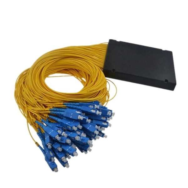
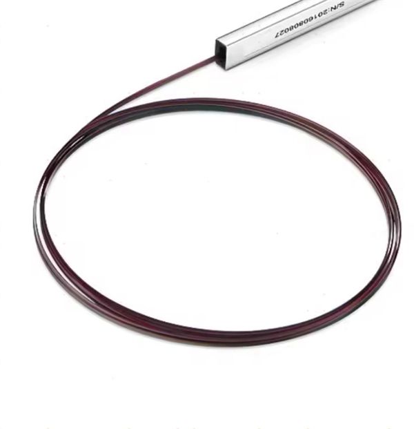
This step-by-step guide aims to provide a comprehensive understanding of the techniques and considerations involved in successfully connecting optical fibers, offering invaluable insights for professionals and enthusiasts in the field. In high-speed data networks, the seamless integration of fiber optic cables with SFP (Small Form-Factor Pluggable) modules is critical for reliable signal transmission. SFP transceivers bridge electrical and optical signals, making them indispensable in data centers, telecom networks, and. Proper connection of fiber optic cables is essential to harness these benefits fully, as even minor errors can lead to significant performance issues like signal loss. This article will guide you through the necessary tools, materials, and methods on how to connect fiber optic cables effectively. This section describes how to install optical transceivers on the SFP or SFP+ ports and connect them to the ports of the peer device using optical fibers according to the network plan. The USG supports both 1 Gbit/s, 10 Gbit/s, and 40 Gbit/s optical modules. The optical modules at both ends are. There are many types of fiber optic connectors, including SC, LC, FC, ST, D4, MU, MT/MPO, etc. These connectors can be divided into single-mode and multi-mode fiber optic connectors according to their structure and purpose. In this tutorial.
[PDF]
A neat, well-organized subpanel bundles wires to conserve space and improve access. Ideally, wire groups are installed in layers and wires are bent at right angles to buses or breakers. Label short sheathing sections (slugs) to indicate which circuits wires serve. Choose the right box based on environment (indoor/outdoor), load capacity, and durability. Check for proper IP/NEMA ratings and material quality. Ensure safe placement: install in dry, accessible areas with good ventilation and at appropriate height (typically ~1. Practice good wiring: secure. Box installation: Make sure that Distribution box has been correctly installed and fixed. Material preparation: Prepare the required circuit breakers, wires, wiring ties and other materials, and ensure that they meet the design drawings and installation requirements. And all the switching and protective devices are installed in the. Wiring distribution panels serve as the central hub and nerve center, routing power from the main service feed to multiple circuits. When setting up such a significant component of industrial, commercial, and utility applications, it's essential to get everything right. Labeling cables at outlets is.
[PDF]
In this Cisco Tech Talk, learn how to view the optical module status on a Cisco switch using the Command Line Interface (CLI). This video demonstrates how to access the optical module status, check for any issues, and monitor the health of your network's optical components. Learn. When optical modules operate on a switch, it is usually necessary to read the module's internal information to understand its working status—such as connection status and real-time metrics like optical power and temperature. Additionally, identifying module information helps detect coding. This chapter describes how to configure the Optical Amplifier Module and Protection Switching Module (PSM). When you plan to replace a configured optical module with a different type of optical module, you must clear the configurations of the old module before you install the new module. By checking module health, compatibility, and digital diagnostics, you can quickly confirm correct installation, detect optical problems, and maintain accurate hardware. Small Form-factor Pluggable modules (SFP module) are the workhorses of modern network connectivity, enabling flexible fiber optic or copper links between switches, routers, firewalls, and servers. Whether you're upgrading bandwidth, replacing a faulty unit, or reconfiguring your topology, knowing.
[PDF]

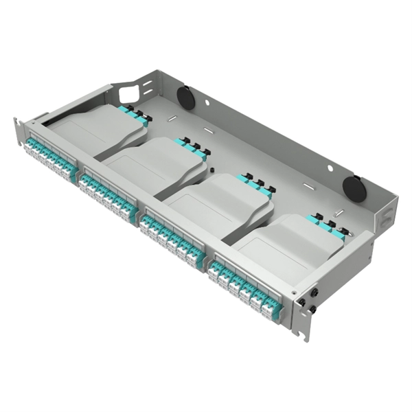
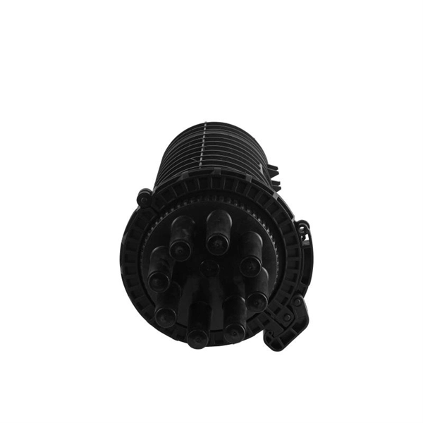
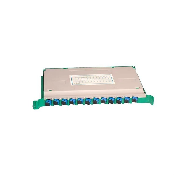
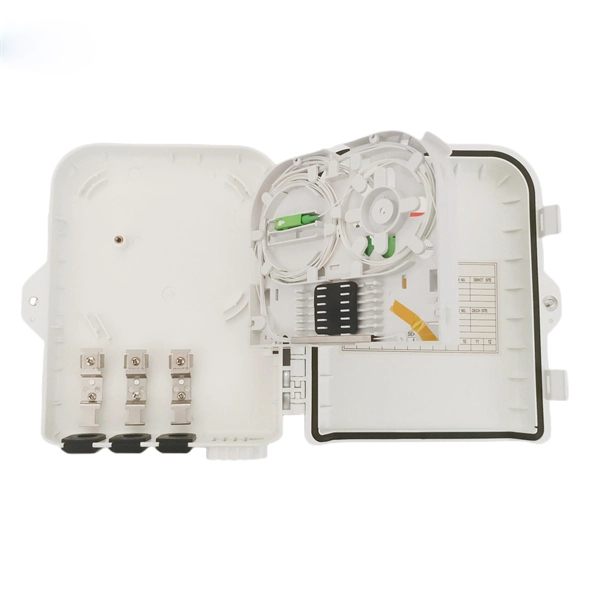
Learn how to install a fiber distribution cabinet step by step, including mounting, cable routing, grounding, and testing for FTTH networks. The installation of a fiber distribution cabinet involves five key steps: site selection, cabinet mounting, cable routing, fiber splicing, and grounding +. This step is very simple, we only need to install brackets on both sides of the optical fiber distribution box, and then fix the brackets to the designated position of the rack with screws. It should be noted that before installing the optical fiber distribution box, the installation direction of. Keeping this page as a placeholder for now. Have any questions? Talk with us directly using LiveChat. Read and understand this procedure (as well as the instructions provided with related assemblies) before beginning an installation. Do not discard this instruction; keep it on hand for future reference. Familiarize yourself to understand the unit's placement in your network. The 1U fiber optic distribution box is used as an example to introduce its structure. Three adapter panels can be installed on the front panel of this fiber optic distribution. Fiber Distribution Hub Installation Procedure - Optical Cable Corporation Products Fiber Copper Hybrid Cabinets, Racks, Enclosures Deployable Solutions Industries Oil & Gas Mining Industrial BroadcastAV Military Commercial Enterprise library & Support Contact Resources About OCC News Careers.
[PDF]
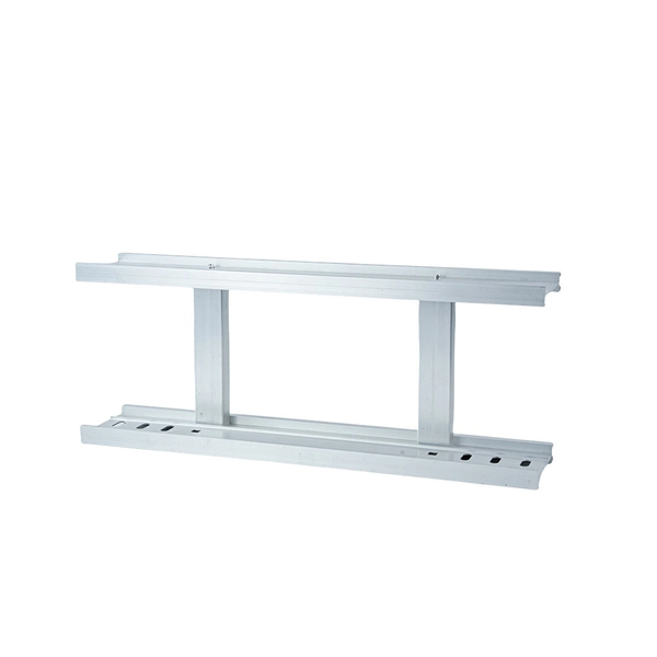
Calm the chaos by following clear current, temperature, and clearance rules from IEC 61439 guidelines and this handy overview from ABB's busbar selection guide: ABB Busbar Applications Handbook. In the power transmission and distribution system, busbar is the core conductive component, which is widely used in high-voltage transmission, data center, new energy, rail transportation, industrial automation and other fields. Different types of busbars have their own characteristics in terms of. Prices of bus bar assemblies vary depending upon quantity ordered. In addition, individual dimensional characteristics, materials, manufacturing techniques, the interconnection scheme, plating finish, insulation, and hardware requirements affect overall cost. Busbars act as the main current highways inside high voltage switchboards, linking incoming feeders. When designing electrical power systems, one of the most critical aspects is selecting the right size for busbars. Busbars are the backbone of switchboards, distribution boards, and electrical panels. The group of busbars are consisting of 5 bars, one for each phase, one for neutral and one. To connect various high voltage (HV) components to the HV system, TE also delivers a wide variety of busbars. In cooperation with the customer, these can also feature TE's Bus Bar Insulation Tubing (BBIT). Busbars provide a safe HV connection on shorter distances. Especially in the area near the.
[PDF]