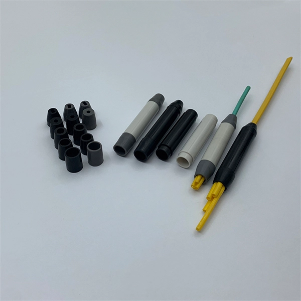
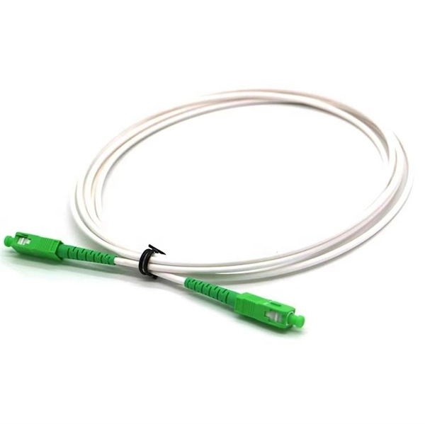
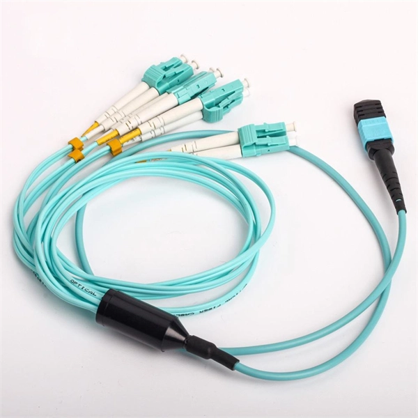
Get the wrong connector type, the wrong polish, or skip proper fusion splicing technique—and you're looking at elevated signal loss, increased back reflection, and a field termination that fails certification. Once you nail the logic chain— raw fiber → protected cable → spliced pigtail interfaces → flexible patching —you control loss budgets, installation time, and maintenance risk. Key takeaway: Treat the four items like a relay team. Each runs a specific leg so your network hits performance targets. In the intricate ecosystem of fiber optic networks, two components play a critical role in ensuring seamless connectivity: patch cords and pigtails. While both are essential for linking fibers to devices or other cables, they serve distinct purposes and are designed for specific scenarios. Executive Summary: A fiber optic pigtail is one of the most commonly specified yet least understood components in structured cabling. Despite their widespread use and numerous advantages, there are some circumstances in which they might not be the ideal option. A fiber optic pigtail is very practical for on-site terminations where fusion or mechanical splicers are used. Preterminated connectors offer several advantages over. Today, I'll show you how to pick the right patch cord or pigtail — step by step. A Fiber Patch cord connects two devices. You plug it into a switch, router, or patch panel. It's ready to use out of the box. A pigtail is for splicing.
[PDF]
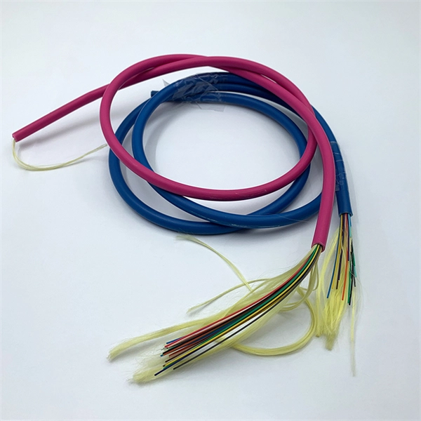
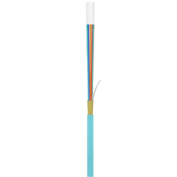
Fiber optic "cable" refers to the complete assembly of fibers, other internal parts like buffer tubes, ripcords, stiffeners, strength members all included inside an outer protective covering called the jacket. Cable provides protection for the optical fiber or fibers within it appropriate for the environment in which it is installed. You will also learn how different aspects of the product can affect budget and design. ■ The Five Key Parts of a Fiber Optic Cable A fiber optic cable. A fiber optic cable consists of five basic components: the core, the cladding, the coating, the strengthening fibers, and the cable jacket. When searching for a fiber optic cable, we need to pay attention not only to the connectors, such as SC to ST fiber cable, LC to SC fiber patch cable, or SC to. A TOSLINK optical fiber cable with a clear jacket. These cables are used mainly for digital audio connections between devices. This advanced cabling solution allows fast, secure data transfer and telecom over long distances. Understanding the components within a fiber optic cable enables. While fiber optic cable itself is cheaper than an equivalent length of copper cable, fiber optic cable connectors and the equipment needed to install them have typically been more expensive than their copper counterparts.
[PDF]
This Technical Brochure describes the induction phenomena (inductive, capacitive and conductive) that can lead to presence of voltage and currents on disconnected cable systems. The optical fiber composite overhead ground wire (OPGW) has been widely used in power transmission lines. Methods of calculation to evaluate those values and touch voltages are detailed and analysed, associated with various. working on cables u al, photocopying, recording or otherwise, without the prior written or use by members of the Energy Networks Association to take account of the conditions which apply to them. Advice should. Literature review: An in-depth literature review covering the modelling and calculations of the conditions relating to faults caused by interactions between fibre optic cables and power cores in submarine cables. Examples of electrically conductive installations where induced voltage may occur could be: • Overhead lines or cables out of opera- tion •.
[PDF]
In 2024, Top exporters of Optical fibre cables, made up of individually s are China ($2,363,805. 65K, 379,127,000 Kg), United States ($1,645,814. 71K ), Mexico ($1,313,955. 67K, 18,156,300 Kg). 17 billion (according to external trade statistics of 117 countries). There are no trade data (2023) for such exporters as Korea. Asian countries collectively account for nearly 50% of global exports, with China dominating in both sectors. Looking at both optical fiber and optical cable, China ranks first with an export share of 29. 6%, followed by the United States (12%) and Mexico (11%), which shows that technology is highly. Volza's Big Data technology analyzes over 3. 5 billion verified shipment records across 203 countries to help exporters and importers identify new Fiber Optical Cable buyers and suppliers, discover profitable markets, and connect with reliable trade partners worldwide. According to Volza's Global. Analyze Fiber Optical Cable export import data and locate key markets, reliable suppliers, and active buyers by utilizing Eximpedia's data-centric platform. Whether you're a supplier looking for high-demand markets or a buyer sourcing Fiber Optical Cable from reliable exporters, Eximpedia's. Find verified buyers and sellers of fiber optic cables in 180+ countries along with their valid phone numbers and email ids. The top 3 Buyer countries for fiber optic cables are “ CHINA ”, “ UKRAINE ”, “ UNITED STATES OF AMERICA ”,.
[PDF]
The price per foot includes the fiber itself, connectors, and basic installation factors, with main drivers being cable type, distance, and any required conduit or termination hardware. This article outlines cost expectations, price ranges, and practical savings. Fiber-optic cable materials typically cost $1 to $6 per linear foot, depending on fiber count and cable type. Commercial building installations with 100-200 network drops generally range from $15,000 to $30,000. Single-mode fiber costs less per foot than multimode fiber, but it requires more. Typically, per drop fiber cabling prices range from $250 – $1000 per drop depending on the type of fiber (OM2, OM3, OM4, or OM5), multi or single mode, PVC or plenum, average drop length, and also the number of fibers in each cable. This. Whether you need singlemode, armored, or indoor plenum, this guide gives you the exact cost per foot of fiber optic cable — including installation — so you can budget without guesswork. Data aggregated from Q1 2026 contractor invoices across Texas, Ohio, and North Carolina. The installation type you choose and the layout of your property determine the total labor and materials needed for your project. Cost for fiber cabling projects.
[PDF]
Abstract: Detecting partial discharges in cable joints is critical for timely defect identification and reliable transmission system operation. The electric field distribution of the optical fiber-implanted cable joint was simulated, followed by electrical performance tests, demonstrating that optical fiber implantation had a negligible effect on the electrical properties of the cable joint. A platform utilizing Mach–Zehnder–Sagnac. The results show that the average sensitivity of the sensor in the 10 kHz–80 kHz range is 71. 0 dB higher than that of the piezoelectric transducer, with a maximum signal-to-noise ratio of 65. To improve the long-term reliability and sensitivity of the sensing system, a novel method for cable joint monitoring based on implanting optical fibers. However, there is an industry gap in the literature about the highly sensitive fiber optic-based PD solution based on the acoustic emission principle. This paper aims to fill such an industry gap. In this paper, the fiber optic-based PD sensing (OptiFender) technology is applied to monitor the PD.
[PDF]
The vertical clearance for overhead fiber optic lines above the highway must be a minimum of 18 feet. The exception is ADSS cables which are approved for installation in the power space by qualified personnel. All aerial cables should be installed clear of any obstructions. The Fiber Optic Association, Inc. (FOA) was founded in 1995 to help develop the workforce to build the fiber optic networks to support a rapid expansion in communications and the Internet. The charter of the FOA was to promote professionalism in fiber optics through education, certification, and. The basic pole height is 7m and the tip diameter is 150mm. In case of special sections, crossing obstacles or roads or railways, the pole height of 8m, 9m, etc. can be selected according to the actual terrain. If the surface is stone, the depth needs to be 0. 9m, and if the surface is other soil. Generally a 12 inch to 24 inch soil separation is recommended as a safety barrier and for locating purposes. 9938 | SuperiorEssexCommunications. com Page 1 of 4 TECHNICAL GUIDELINE July 30, 2020 TG030 Rev. FIBER is used for relocating any fiber optic cable from one location to another. Field conditions will vary, so the actual location. to n utral comm.
[PDF]
Use this worksheet to input values for all variables that will impact your system's performance. After entering your values, please ensure you click the 'Calculate Link Loss' button at the bottom of the page to generate your total link loss. Add connectors, splices, bends, and safety margin easily. See results instantly above the form, then adjust values. Choose a mode, then enter values and optional losses. All calculations use base-10 logarithms. mW must be greater than zero. Used only in measured attenuation mode. Length is needed. The power budget refers to the amount of fiber optic cable plant loss that a datalink (transmitter to receiver) can tolerate in order to operate properly. Sometimes the power budget has both a minimum and maximum value, which means it needs at least a minimum value of loss so that it does not. To detect whether the link runs properly, the following calculation should be performed. It is often the case to calculate the maximum signal loss across a given fiber link during optical cable installation. First, you should be aware of the fiber loss formula: The Total Link Loss = Cable. Therefore, it is very important to calculate the fiber loss and take appropriate steps. In order to get the most reliable results, an Optical Time Domain Reflectometer (OTDR) trace of the actual fiber connection should be completed. This will provide you with the real.
[PDF]
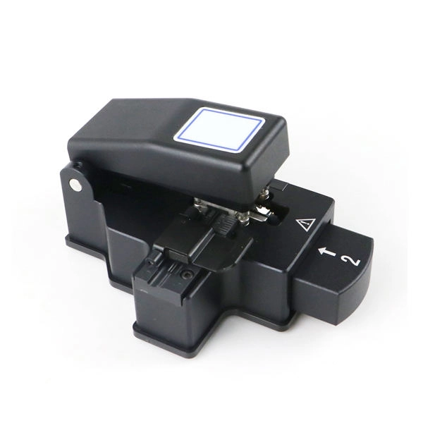
We terminate fiber optic cable two ways - with connectors that can mate two fibers to create a temporary joint and/or connect the fiber to a piece of network gear or with splices which create a permanent joint between the two fibers. Proper connection of fiber optic cables is essential to harness these benefits fully, as even minor errors can lead to significant performance issues like signal loss. These terminations must be of the right style, installed in a. Running fiber internally involves extending this high-speed link from the service entry point to a centralized location, such as a dedicated media closet or network rack. This DIY effort is undertaken to maximize performance, improve aesthetics, or relocate the Optical Network Terminal (ONT) to a. In this video, we'll guide you through preparing and terminating fiber optic cables using SimplyFiber products, known for their high quality, ease of use, and reliability. more Audio tracks for some languages were automatically generated. Two types of splices are used in fiber optic cabling one is Mechanical the other is Fusion. Whether you're installing a new network, expanding an existing one, or. But here's the thing: how you connect fiber optic cable really matters. A shaky connection means weaker signals, dropped streaming, or slow uploads. Get the hookup right, and you'll enjoy streaming, gaming, and video calls without interruptions.
[PDF]
The modern world relies heavily on electrical and communication cables that must be managed and supported across vast distances in commercial and industrial settings. A cable tray is an organized support structure designed to secure and route these insulated electrical cables. In the electrical wiring of buildings, a cable tray system is used to support insulated electrical cables used for power distribution, control, and communication. Cable trays are used as an alternative to open wiring or electrical conduit systems, and are commonly used for cable management in. Whether you're planning a new office setup or upgrading your existing network, the choice of a cable tray system plays a significant role in ensuring the reliability and scalability of your structured cabling solution. It acts as a. en completely installed, without damage either to conductors or structural system use maintain spacing or to keep cables in place when the tray is ect the minimum bend ra-dius for cables as they exit the bottom of the cable tray. A rung spacing of 6 to 9 inches (150 to 230 mm) is preferable when. Explore various cable tray types and sizes for electrical installations. Learn about ladder, perforated, solid-bottom, wire mesh, and channel trays in this complete guide. What is Cable Tray Systems? 1.
[PDF]
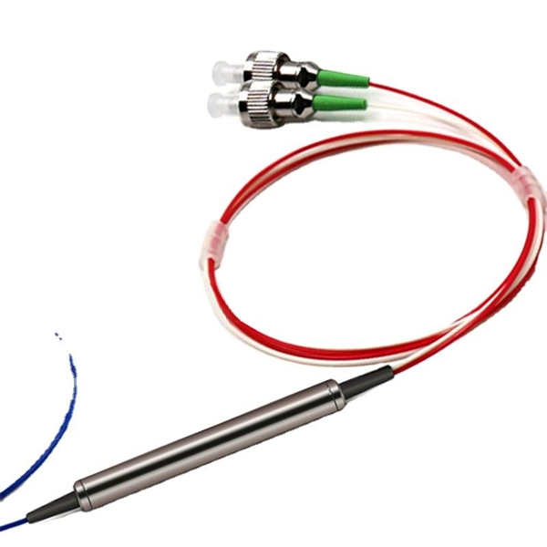
A PLC splitter is a passive optical device that divides one incoming optical signal from an input fiber into multiple output signals across several output fibers. PLC splitters utilize a planar lightwave circuit chip made of silica glass waveguides to distribute the optical power. PLC optical splitters (planar waveguide optical splitter) is a key component in optical fiber communication networks and is widely used in optical fiber distribution systems such as FTTH (fiber to the home) and PON (passive optical network). This passive yet sophisticated device utilizes integrated optics technology to split a single input signal into multiple. PLC splitter, also called Planar Waveguide Circuit splitter, is a device used to divide one or two light beams into multiple light beams uniformly or combine multiple light beams to one or two light beams. This helps share signals in fiber optic networks. Pick the split ratio that matches what you need. Lower ratios work for fewer users. Choose the connector type like SC, LC, or FC.
[PDF]
Naficon Liitin Oy, the parent company based out of Finland is one of the most trusted suppliers for telecom, data centers and utility across Northern Europe. Naficon Fiber Optic Manufacturing LLC in Dubai, UAE serves as a major Manufacturing and Supply Centre in the Middle East. We are a leading manufacturer of Optic Fiber Cables in the United Arab Emirates. With advanced technology, strict quality standards. The United Arab Emirates (UAE) is a thriving hub for fiber optic cable manufacturing, offering advanced solutions to meet the region's growing demand for high-speed internet and reliable telecommunications infrastructure. Here, we explore some of the leading fiber optic cable manufacturers in the. The best connection for your application. New web catalogue, with productfinder and new search function. Search the complete range of products of Lapp Group. This website uses cookies and similar technologies (hereinafter "cookies"). Providing a happier, richer future through providing solutions for copper and optical communication for the past 20 Years. Established to meet the evolving needs of the telecommunication infrastructure network, AFOC focuses on delivering innovative, customized, and competitive optic fiber cable products. NAFICON is a fiber industry expert with over 30 years of manufacturing legacy.
[PDF]
Proper fiber optic termination is a crucial process for ensuring the reliability, performance, and long-term durability of any fiber optic network. The process of fiber optic cable termination is the essential act of connecting fiber optic cables to devices, patch panels, or other. Fiber optic joints or terminations - where cables are terminated - are made two ways: 1) connectors that mate two fibers to create a temporary joint and/or connect the fiber to a piece of network gear (left) or 2) splices which create a permanent joint between the two fibers (right). Thus, you will put the cable across the points, stretch it to determine length, cut it accordingly, and place the connector on each end. After that, the patch panel attaches to it. Each cable has a connector attached. A. Once fiber optic cables have been successfully placed, we can focus on managing the ends of the fibers. This process depends on the project's needs and identifying a solution that aligns with the current situation. We can make suggestions that typically benefit the current circumstances and result. Where copper twisted pairs tend to terminate with an RJ45 plug, fiber optic connectors come in all sorts of shapes and sizes, with all manner of different use cases in mind. An optical fiber connector is used to join optical fibers where a connect/disconnect capability is required.
[PDF]
A practical, engineering-focused guide to planning and installing underground fiber optic cables with the right cable structure, trench design and protection level for long-life, low-risk networks. Match trench method with the correct underground fiber structure (GYTS . Installing fiber underground is one of the most durable ways to protect a network's backbone — when it's done right. Direct-burial fiber cable eliminates the need for continuous conduit runs and can be faster and more cost-effective on long, open runs. But because the cable sits in soil exposed to. 1. 01 This procedure provides general information for the installation of Prysmian fiber optic cables in direct buried applications. The methods described are intended for guideline use only, as it is impossible to cover all the various conditions that may arise during an installation. Individual. ion) and “ Installed” (after installation). The following formulas may be used to determine general guidelines for installing Corning Optical Communications fiber optic cable; however, refer to the cable specifi simply double the minimum working bend radius. Split cable guides and split 40-in. Fiber optic cable transmits data as pulses of light through thin strands of glass, offering superior bandwidth and distance capabilities compared to traditional copper wiring.
[PDF]
Tray cables (TC) are multi-conductor cables designed and rated for installation in cable trays and raceways or supported by messenger wires. Cable tray may be used as the Equipment Grounding Conductor (EGC) in any installation where qualified persons will service the installed cable tray system. There is no restriction as to where the cable tray system is installed. The metal in cable trays may be used as the EGC as per the limitations. maintain spacing or to keep cables in place when the tray is ect the minimum bend ra-dius for cables as they exit the bottom of the cable tray. A rung spacing of 6 to 9 inches (150 to 230 mm) is preferable when the cable tray cont d for instrumentation and control applications that require. The most frequently used tray cables are: Type TC – Tray Cable – (NEC Article 336) –Power and control tray cable type TC is a factory assembly of two or more insulated conductors, with or without associated bare or covered grounding conductors, under a non-metallic jacket. TC cables are rated for. Hubbell Wiring Device-Kellems and Hubbell Premise Wiring are divisions of Hubbell Incorporated, a U. headquartered manufacturer with over 130 years of supplying solutions for the electrical and data markets. At the panel, the cable is installed in conduit (s) for the vertical.
[PDF]