The laser diode market in Kazakhstan is experiencing growth, driven by expanding applications in sectors such as telecommunications, healthcare, and consumer electronics. Laser diodes find use in devices such as optical transmitters, barcode scanners, and laser pointers. Technological advancements. Blue Laser Diodes Market size was valued at USD 245 million in 2024 to USD 370 million by 2032, exhibiting a CAGR of 6. 2% during the forecast period. 7 billion in 2024 and is anticipated to grow at a CAGR of 14. 4% between 2025 to 2034. Rapid proliferation of high-power laser diodes in autonomous vehicle technologies. 744 USD Billion in 2024. The market drivers for the Blue Laser Diodes Market can be influenced by various factors. These may include: Growing Demand in Consumer.
[PDF]
The third part represents the number of spots in the beam splitter. The naming principle of the beam splitter is easy to illustrate with the following example. The models listed in the following table are examples After years of exploration, we can maintain all process parameters of the beam splitter stable and. A beam splitter or beamsplitter is an optical device that splits a beam of light into a transmitted and a reflected beam. It is a crucial part of many optical experimental and measurement systems, such as interferometers, also finding widespread application in fibre optic telecommunications. a laser beam) into two (or sometimes more) beams, which may or may not have the same optical power (radiant flux). Newport offers a wide variety of Beamsplitters in various shapes. Circular beamsplitters, plate beamsplitters and cube beamsplitters can be purchased for polarizing or non polarizing beamsplitting. Thorlabs offers a wide range of optical beamsplitters. Our plate beamsplitters have a coated front surface that determines the beam splitting ratio while the back surface is wedged and AR coated in order to minimize ghosting and interference effects. Additionally, beamsplitters can be used in reverse to combine two different beams into a single one. Beamsplitters are often classified according to their construction: cube or plate.
[PDF]
You simply multiply the number of splices by the estimated loss per splice. It's that easy! ✨ Let's say you have a long fiber run that requires 4 fusion splices to connect different cable segments. 4 dB is the total attenuation you'll add to your loss budget just for the. Fusion splicing is the process of fusing or welding two fibers together usually by an electric arc. Fusion splicing is the most widely used method of splicing as it provides for the lowest loss and least reflectance, as well as providing the strongest and most reliable joint between two fibers. There are several ways to know the number of multi-spliced cores. For example, 12 core fibers, 12*2=24 cores, 12 cores at the beginning and 12 cores at the end; 2. Count the number of optical fiber. Calculating the total loss from splices in a cable run is wonderfully straightforward. Connectors: Total number of connectors in design. Laser: A device which produces a single frequency light. The guide provides the complete workflow, covering safety precautions, tool selection, fiber preparation, fusion operation, quality control, and. Recommendation ITU-T L. 12 specifies splices of single-mode and multimode optical fibres. It describes suitable procedures for splicing that should be carefully followed in order to obtain reliable splices between single optical fibres or ribbons.
[PDF]
A T-tap wire connector, also known as a T-splice connector, is used to tap into existing wires and is characterized by its T-shaped design with three points of entry for wires. This allows you to install the connector on a wire and tap into it from the third entry point. The wall-mounted bracket features an integrated coupler for quick and easy installation, enhancing overall work efficiency. Corrosion-resistant galvanized coating protects against bad weather, moisture, and rust - ensures a long service life even in harsh environments. T-shape design provides both. How can we improve? Choose from our selection of T-connectors, including stainless steel pipe and pipe fittings, brass and bronze pipe and pipe fittings, and more. Same and Next Day Delivery. The NavePoint 00406777 electro zinc plated wire mesh cable tray t-shaped wall bracket is an ideal solution for neatly routing and organizing cables. Fast Docking Coupler Bar for Wire Mesh. Toolless Adapter Fitting for Fiber. The L-com LC-CRP100 T-shaped wall bracket offers a perfect way for mounting and securing the wire mesh cable tray to the wall. Made by Quest Manufacturing, this add on accessory is durable and reliable, and will hold the wire mesh safely, so you can place cables & wires in. Design Shape This bracket is designed with a T shape which provides support.
[PDF]
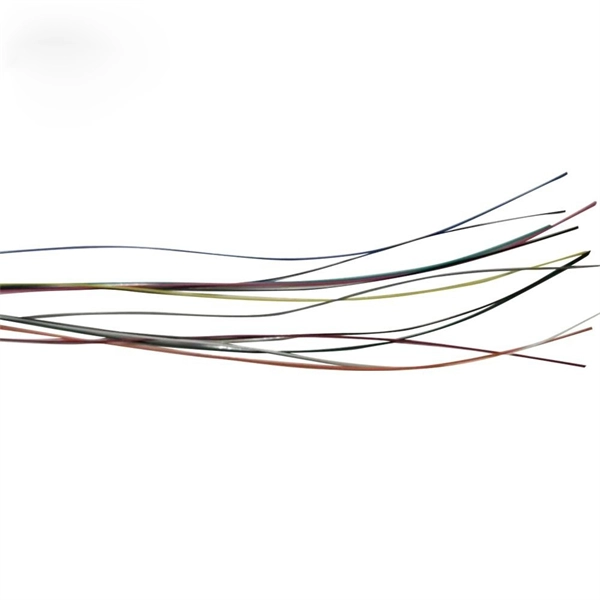
The number of optical cores in an optical fiber is the total number of equipment interfaces multiplied by 2, plus 10% to 20% of the spare quantity, and if the communication mode of the equipment has serial communication and equipment multiplexing, you can reduce the number of cores. The number of. There are several ways to know the number of multi-spliced cores. For example, 12 core fibers, 12*2=24 cores, 12 cores at the beginning and 12 cores at the end; 2. If. This article will walk you through the basics of fiber optic cores and provide practical guidance for selecting the suitable fiber optic cable to meet your networking needs. Fiber cores are the heart of fiber optic cables, transmitting light signals that carry data. Made from either high-quality. By adopting the TIA/EIA‑598C standard, you gain a universal “language” of colors that speeds identification, reduces miswiring, and enhances safety across cable jackets, connectors, buffer tubes, and splice trays. Error Reduction: A standardized palette prevents costly mis‑splices and. The number of cores is the number of glass fibers contained in each fiber. First of all, clearly know the number of wiring points in this layer, calculate the number of switches, and whether the connections.
[PDF]
Professional home circuit calculator per NEC Article 210 and 220. Determines the total number of branch circuits, wire sizes, breaker ratings, and GFCI/AFCI protection requirements for residential electrical systems. Covers general-purpose lighting circuits, small appliance circuits, laundry. Before determining the required number of circuits and associated calculations, let's define and differentiate between branch circuits, general-purpose lighting branch circuits, and individual branch circuits. According to NEC Article 100 – Definitions: Branch Circuit: Refers to the conductors. Before we dive into calculations, let's get familiar with a few essentials: 1. Your Project's Total Power Demand This isn't just adding up wattages randomly. Think of your home as a busy kitchen—not every appliance runs at once. Do you really need the hair dryer, microwave, and vacuum running. Professional electrical panel schedule tool for creating detailed load distributions, calculating circuit loads, balancing phases, and ensuring NEC compliance for electrical distribution panels. Panel schedules are essential for electrical system documentation, load analysis, and NEC compliance. Compute the branch circuits, feeders, service-entrance conductors, and wire protection. How do you determine the minimum number of general lighting and general-use branch circuits required by the NEC for dwellings? A.
[PDF]
Single-mode fiber optic cable typically has a single core. This means that it consists of a single strand of glass fiber that carries light signals. The core is the central part of the cable through which the light travels, surrounded by a cladding layer that helps guide the light. One key factor is the number of cores, which impacts how much data you can transmit. This post will guide you through understanding fiber optic cores and selecting the perfect cable for your needs. Single-mode: A. The number of optical cores in an optical fiber is the total number of equipment interfaces multiplied by 2, plus 10% to 20% of the spare quantity, and if the communication mode of the equipment has serial communication and equipment multiplexing, you can reduce the number of cores. The number of. Common fiber cores include 1 core, 2 cores, 6 cores, 8 cores, etc., and there are many types. The total number of cores for a 1pc fiber patch cable is calculated as the number of. The most common type of fiber optic cable used in telecommunications is single-mode fiber, which usually has a single core.
[PDF]