Connect the Ethernet cables: Connect one end of an Ethernet cable to the PoE switch's uplink port, and the other end to the network router or modem. Then, connect the devices that require power to the PoE ports on the switch using Ethernet cables. A Power over Ethernet (PoE) switch is a device that enables the transmission of both power and data over a single Ethernet cable. This eliminates the need for separate power cables and allows for flexible placement of network devices in locations where power outlets may be limited or absent. In. The first thing you need to do is connect your switch to an electrical outlet so it is powered on. This means you can power devices such as wireless access points, IP cameras, and VoIP phones using the same cable that provides network connectivity. 3at (PoE+), and. One of the biggest advantages of copper twisted pair Ethernet cable (also called Category cable) is it's ability to perform two critical functions at the same time: When these functions are simultaneously performed, it is known as PoE or Power over Ethernet. It utilizes efficient low-voltage 43 to 57 VDC over twisted-pair network cabling, such as Category 6A, Category 6, and Category 5e. This means PoE can be installed without risk to.
[PDF]
PoE delivers 44-57v of DC power over unshielded twisted-pair wiring for terminals consuming up to 25 watts, depending on the version of the standard in use. Power over Ethernet (PoE) describes any of several standards or ad hoc systems that pass electric power along with data on twisted-pair Ethernet cabling. This allows a single cable to provide both a data connection and enough electricity to power networked devices such as wireless access points. Imagine powering your entire network infrastructure through the same cables that carry your data, eliminating the need for separate power supplies and electrical outlets near every device. This isn't a futuristic concept—it's the reality that power over Ethernet has made possible since 2003. While PoE doesn't add Ethernet data capabilities, it does offer expanded options for how and where Ethernet end devices can be. Power over Ethernet is a technology that allows IP telephones, wireless LAN Access Points, security network cameras and other IP-based terminals to receive power, in parallel to data, over the existing CAT-5 Ethernet infrastructure without the need to make any modifications. The simple nature eliminates the need for multiple power supplies, and allows connectivity to devices where power outlets are not available. Instead of running a separate power line to each device, PoE lets the Ethernet cable (usually a Cat5e or Cat6 cable) carry both the network connection and.
[PDF]
Power over Ethernet (PoE) is a technology that enables the transmission of electric current and data simultaneously over Ethernet cables, eliminating the need for separate power cables. This section wil.
[PDF]
The IEEE standard for the base PoE switches is 802. 3at for PoE+, and 802. PoE and PoE+ transmit power over two pairs of twisted-pair wires in their cables, while the PoE++ variants use four pairs of twisted-pair wires. The splitter is the silver and black box in the middle between the wiring junction box (left) and the access point (right). The PoE connection eliminates the need for a nearby power outlet. In another common configuration, the access point or other connected device includes internal PoE splitting. Power over Ethernet (PoE) switches combine data and power delivery into a single Ethernet cable, simplifying deployment of devices such as access points, IP cameras, VoIP phones, and IoT equipment. PoE does not reduce network speed, does not waste excessive power when proper cabling standards are. Therefore, everyone is concerned about whether PoE switches will affect speed. Key Benefits of Power over. PoE switches (Type 1) comply with the IEEE 802. 3af standard, which specifies the maximum power delivered over Ethernet cables.
[PDF]
The 5-Port Gigabit Ethernet PoE+ Switch with SFP Port from Intellinet Network Solutions passes both data and electrical power to a number of PoE-compatible devices via standard Cat5e or Cat6 network cabl.
[PDF]
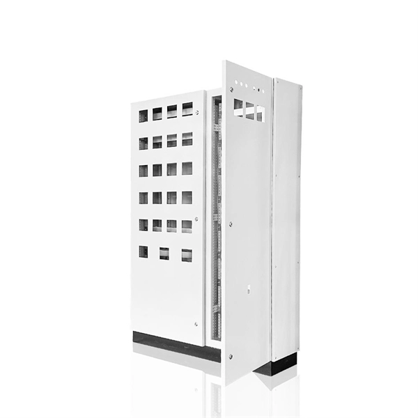
A core switch is a crucial component of a network infrastructure that serves as the backbone of a network. It's a high-performance switch that provides high-speed connectivity between different network segments, which may include access switches, distribution switches, and routers. Engineered to aggregate massive volumes of data from distribution switches, it provides ultra-low latency and maximum throughput to ensure uninterrupted routing and packet. It's more than just a switch; it's the central nervous system of your network infrastructure. Its primary function is to rapidly forward data packets between. Professional networks are structured using a three-tier hierarchical model to ensure scalability and efficient traffic management. This model divides the network into three functional layers: the Access Layer, the Distribution Layer, and the Core Layer. The Access Layer sits at the edge, using. Core switches are the focal point for traffic control between access and distribution switches. They perform a vital function in ensuring the network's reliability and stability because they are in charge of routing data across the network infrastructure in a reliable and timely manner. They operate at the data link layer (Layer 2) or the network layer (Layer 3) of the OSI (Open Systems Interconnection) model, facilitating the communication of devices on a network by receiving, processing.
[PDF]
8032 is the gold standard for implementing ring networking topographies. When implemented properly, G. 8032 management safeguards Ethernet traffic and achieves recovery times of less than 50 milliseconds (ms). This document provides basic background information regarding adding ring redundancy in your wired Ethernet networks. It will explore the N-Tron proprietary protocol N-Ring and how it is a step up from IEEE Spanning Tree and Rapid Spanning Tree Protocol (STP, RSTP). Examples for creating a. Ethernet Ring Protection Switching (ERPS) is an effort at ITU-T under G. 8032 Recommendation to provide sub-50ms protection and recovery switching for Ethernet traffic in a ring topology and at the same time ensuring that there are no loops formed at the Ethernet layer. This ITU-T specification is. Device Level Ring (DLR) is a Layer 2 protocol that enables redundancy in a ring topology, providing fast network fault detection and reconfiguration for industrial networks. DLR is an EtherNet/IP™ protocol that is defined by the Open DeviceNet® Vendors' Association (ODVA). 8032 management safeguards. The ITU-T G. ERPS is similar to spanning-tree protocols, but ERPS is more efficient because it is customized for ring topologies.
[PDF]
They support devices like IP cameras, wireless access points, and IoT devices, enabling placement in remote areas without nearby power outlets, a capability that regular switches lack as they can only handle data transmission and require a separate PoE injector for power supply. Network switches form the backbone of any Local Area Network, or "LAN" (pronounced "lan") for short. On this page you will learn what differentiates a PoE enabled switch from a regular LAN switch, when you should use a PoE switch versus a PoE injector and, what exactly is PoE (Power over Ethernet). A PoE (Power over Ethernet) switch is a network switch that delivers both power and data through a single Ethernet cable to connected devices such as IP cameras, VoIP phones, wireless access points, and IoT devices. This eliminates the need for separate power adapters, reducing cable clutter and. In today's blog, we'll explain what a PoE switch is and how it powers devices through one Ethernet cable. We'll also look at the different types of PoE switches, their benefits, and how they can be used in real-world situations. What Is PoE (Power. PoE switches deliver power and data over Ethernet cables, eliminating the need for separate adapters. For businesses, this simplifies deployment of IP cameras, access points, and VoIP.
[PDF]
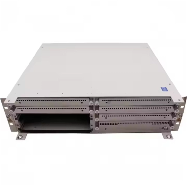
The number of core switch ports is large, usually modular, and can be freely matched with optical ports and Gigabit Ethernet ports. The general core switches are Layer 3 switches, and various advanced network protocols such as routing protocol/ACL/QoS/load balancing can. Does every network need a core switch? Can a router be used instead of a core switch? How do I determine the bandwidth requirements for my core switch? What security features should I look for in a core switch? How often should I update the firmware on my core switch? What are the key performance. Home / Ethernet Switch / Do I need a core switch? The simple answer is “yes. ” Every complex network comprises multiple computers and devices. To route the traffic and improve the performance of the network, you must have a proper mechanism. What would you employ to simplify the network? The core. ● Up to 28 native nonblocking 40/100 Gigabit Ethernet QSFP28 ports. 3-GHz x86 CPU with 8 cores and 32 GB of DDR4 memory. ● Up to 960 GB of SSD. rity to ensure guests and property peaceful and safe. Our solutions provide stable and continu arge commercial buildings host many separate entities. The primary function is to access user data or aggregate some switch data at the access layer. This kind of switch can configure Vlan simple routing protocol and some simple. The number of conventional switch ports is generally 24-48.
[PDF]
Check the steps ① whether the user network card is disabled, ② check whether the network cable is normal with a network cable tester, ③ replace the optical modem LAN port or other ports of the router and switch to test whether normal. Fiber optic networks are celebrated for their speed and reliability, but even the best systems can encounter problems. When issues like signal loss, slow speeds, or intermittent connectivity arise, systematic troubleshooting is key. This guide will walk you through diagnosing and resolving common. We have a fibre run, SM, 650 meters, with Level1 dumb switches at each end, I get Link lights at both ends, but there's no network traffic. Switch A is on the router end, devices connected to this switch get DHCP leases and can browse the internet without issue. These high-speed, high-capacity communication networks are increasingly replacing copper cables, offering superior performance and. However, even the most advanced fiber-optic networks can encounter issues that disrupt performance. This comprehensive guide delves into the most common FTTH problems faced by users, providing detailed troubleshooting steps and real-world solutions. Whether you're a network engineer, IT manager, or service provider, understanding these challenges and how to address them is critical for maintaining high-performance, reliable.
[PDF]
Frequent status changes from up to down or vice versa in the ports logged by the switch port syslog indicates a port flap. On a big industrial plant we've replaced an old HP switch with a brand new couple of C2960x switches in stack configuration and ever since then, every 6/8 hours or so, the two fiber optics links of switch #2 go down at once. These are connected to a ring of 3 similar other access switches, that. EX4650 2-switch virtual chassis, running version 19. 2, optic p/n 740-031981 (SFP+-10G-LR) is plugged into port xe-0/0/10 and connected to an ISP via single mode fiber. Nothing special is configured on the port, it is running at 10G speed, show interfaces diagnostics optics shows that it's. This article describes steps to diagnose the Continuous port flapping on a FortiSwitch. Verify Cable Connection: Ensure the cable is properly connected between the switch port and the end device. Run the command below on FortiSwitch multiple times and check the. Real head scratcher this morning that I'm hoping someone can help me with! The port on our core switch (HP A5500) that our Smoothwall box is connected to keeps going up and down. Port flapping, also known as link flapping, causes a switch port's state to fluctuate between up and down within concise periods of time. This instability caused by flapping ports affects network connectivity. Port flapping is a common network issue that can disrupt communication between devices and degrade overall network performance.
[PDF]
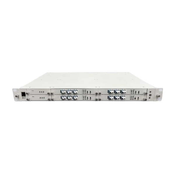
The operating principle of an OCS is similar to telephone circuit switching. When two ports need to communicate, the controller configures a path in the optical switch matrix, using optical components to route the optical signal from one fiber to another, forming an independent. Optical switching represents a fundamental technological evolution, shifting data routing from the domain of electrons to the realm of photons, or light. This transition allows data to remain in its native optical form as it travels through fiber optic networks, eliminating the need for. Optical switches are devices that route light signals from one path to another without converting them into electrical signals first. They're a core component in fiber-optic networks, where data travels as pulses of light through glass fibers. Every time that light needs to change direction or jump. Optical switches, a key component in modern network infrastructure, are devices used in optical fiber networks for signal management. Unlike traditional electrical switches, which transmit data as electrical signals, optical switches handle data transmission in the form of light. These devices play a critical role in modern optical networks by enabling dynamic reconfiguration, wavelength routing, and protection switching. In this article, we will explore the fundamentals of optical switches, their types, and their applications in various fields. An optical switch is a.
[PDF]
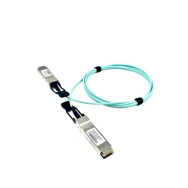
To connect a fiber, align the optical connector with the optical port and gently insert the optical fiber into the port. A fiber adapter (also called a flange) is a fiber connection component. An active optical cable (AOC) is a fixed-length optical fiber with optical modules at both ends. It can be directly connected to an optical port on a device. Table 10-3 lists the models and attributes of. Optical modules are widely used in switches, network interface cards (NICs), routers, and other communication devices. During use, reading optical module information helps understand its real-time operating status, enabling faster troubleshooting of link abnormalities. Solution: To solve this problem, you can follow these steps: Check if the fiber and optical modules are compatible. Perform a. All other trademarks and trade names mentioned in this document are the property of their respective holders. The purchased products, services and features are stipulated by the contract made between Huawei and the customer. Major causes of the interface physically down event include hardware and software failures. Hardware failures: include hardware. Step 1: Antistatic strap must be worn to prevent static damage. Step 2: Take out the optical module, ring and label up, the gold finger is facing down, Note that the right and the negative can not be reversed.
[PDF]
This technology sends data and delivers power from a Power Sourcing Equipment (PSE) to IoT devices such as IP phones, security cameras, wireless access points, etc., using the copper wires in an ethernet cable. This eliminates the need for a separate power source for said devices. A PoE switch is a special network switch that sends electricity and internet data through one regular Ethernet cable (like the ones you use for Wi-Fi or computers). Instead of needing separate power plugs for devices like cameras or sensors, a PoE switch powers them up while connecting them to the. A PoE switch is a regular Fast Ethernet or Gigabit network switch that has Power over Ethernet functionality integrated. This allows network devices like IP cameras, wireless access points, and VoIP phones to receive power without needing separate electrical wiring. This guide breaks down how PoE. Power over Ethernet (PoE) answers the problem of reducing infrastructure costs. This reduces the complexity of installing in awkward locations.
[PDF]
Insert a compatible SFP transceiver into the converter's port, making sure it matches the network's media type and speed. Then, connect one end of the fiber cable to the transceiver and the other to the appropriate port on a switch, router, or another media converter. Fiber media converters translate copper's electrical signals into fiber's optical signals, and back again. This allows networks to extend beyond the 100 m copper limit while gaining higher bandwidth and resistance to electromagnetic interference. In the illustrated setup, each LAN links to a. A fiber media converter is a networking device that allows you to convert a signal from one medium to another. This allows you to connect devices that use different types of cabling, such as a computer. While fiber optic ports are becoming increasingly common on networked electronics, the majority of connected devices still rely on RJ45 twisted pair connections. To help bridge the copper-fiber divide, media converters and transceiver modules (also known as SFPs or mini-GBICs) are often required. Use Fiber Media Converter in Your Network Media converters today are widely deployed in all. It is a device used to convert fiber optic cables to Ethernet cables to provide better connectivity. It is necessary to convert fiber optic signals to Ethernet signals because many network devices can only communicate with Ethernet signals. Fiber optic cables are known for the unmatched speed.
[PDF]