Check the electrical load and ensure that the sensors do not exceed the 10 Amp maximum. Check each wire for damage that may lead to a short. Check the tightness of electrical connections along the power. Understanding how to safely and effectively test a breaker box with a multimeter is a crucial skill for any homeowner or electrician. Regular testing can help identify potential problems, prevent electrical hazards, and ensure the reliable operation of your electrical system. Ignoring this vital. When devices in your new box don't work, you start by testing the circuit. You will want a voltage tester (doesn't need to be a voltmeter) for this job. The very cheapest one you can find at a local hardware store (or online) will work great. In the merger we can see a red wire and a black wire connect the red wire to the megger's line terminal and then. This article summarizes inspection of the building electrical panel, main panel, or electrical distribution and sub panels. A continuity tester is the simplest tool for the specific task of checking for continuity.
[PDF]
The total interruption time for a modern high-voltage SF6 circuit breaker is typically between 40 to 60 milliseconds on a 50Hz grid, or 2 to 3 cycles. This is the total time from the trip signal to the final arc extinction, a critical parameter for grid safety. While knowing the total time is a. When a SF6 circuit breaker (CB) hits its critical low pressure, its fault interrupting capability can be compromised. Most TOs protect against this by either auto-opening the CB prior to reaching the critical low-pressure level or by blocking the CB from tripping (when it reaches the critical. The protected zone is defined and limited by different things depending on the protection function. Definite time delay means that the protection operate time dose not change or depend on the fault type or the fault current magnitude. Instead of oil, air, or a vacuum, a sulfur hexafluoride circuit breaker uses sulfur hexafluoride (SF 6) gas to cool and quench the. Page 1 Content Instruction Manual circuit- breaker GL317 With spring operating mechanisms FK3- 4 Administrator First issue Compiled by Approved by 19- 11- 2012 J. Texier Imagination at work Grid Solutions 04- 2017 D1736EN/03 GE Information 1/10. Page 2 Content Instruction Manual This. A comparison of the time it takes protective devices to operate when certain levels of normal or abnormal current pass through them. LV circuit breaker ratings.
[PDF]
If your breaker box lacks a main breaker 3, look for a split-bus panel 4 design with up to six main disconnects at the top section, or check outside for a separate main disconnect near your meter. In emergencies, you may need to shut off multiple breakers. Older homes often have panels that predate modern requirements, and in some cases, subpanels or unique building designs eliminate the need for a main breaker. An electrical panel, often called a breaker box or distribution board, is a critical component of a home's electrical system. It serves as. The distribution box (DB box) helps safely and efficiently distribute electrical power. Today, electrical systems are essential for homes and industries. What size distribution box do you need for a house? How do you know which circuit breaker to use? Can you add more breakers later? Why do you need GFCI or AFCI breakers? Choosing the right size and setup for your distribution box keeps your electrical system safe and working well. Also called a distribution board, panel board, breaker panel, or electric panel, it is the central hub in an electrical system that divides incoming power into various subsidiary circuits. I contend that in order to disconnect the power to the distribution panel, you have to open both the normal and generator circuit breakers (cannot be disconnected by a single breaker). The main disconnect is usually 200 amps but can sometimes be as low as 100 amps.
[PDF]
Electric recommends these steps to restore power safely when your circuit breaker trips. Turn off and unplug devices on the affected circuit. Locate your electrical panel and identify the tripped breaker. Reset the breaker by switching it fully off, then back on. Plug in devices one at a time. To effectively troubleshoot a tripping breaker, you should begin by identifying potential causes, such as overloaded circuits, short circuits, or faulty wiring. With a little investigation, you can often pinpoint the issue before considering a call to a professional. Knowing how to troubleshoot. Resetting a circuit breaker is generally simple, but it must be done carefully to avoid risk. This prevents a power surge when the circuit is. More often than not, the culprit is a tripped circuit breaker—your home's built-in safeguard against electrical overloads, short circuits, and ground faults. While the idea of opening an electrical panel might feel intimidating, resetting a breaker is a straightforward process when approached with. Before approaching your electrical panel, locate the affected circuit and reduce the load on it. Immediately turn off and unplug any high-wattage appliances, such as space heaters, hair dryers, or toasters, that were in use when the power went out to prevent an immediate overload upon resetting. Often, the culprit is a tripped breaker in your electrical panel, also known as a.
[PDF]
A relay protection tester is a core device used to verify the performance of relay protection devices. Its working principle can be summarized as “signal excitation – behavior detection. ”. Circuit principle of relay protection tester 1, input AC220V power output control relay K1 is approved by the insurance into the dual voltage regulator for T1 input carbon brush, through large knob to adjust the power into the isolation transformer T1 T2 (part-time riser), heat flow device points. When the transformer wiring type is Y/Y (Y0), the test wiring is very simple: when testing phase A, the tester IA is connected to the phase A of the high voltage side, and the tester IB is connected to the phase a of the low voltage side. ” The tester has a built-in high-precision programmable power supply, capable of simulating various operating. This handbook covers the code of practice in protection circuitry including standard lead and device numbers, mode of connections at terminal strips, colour codes in multicore cables, dos and donts in execution. The following is a detailed summary. This Playlist is assigned to sessions of protection Relays Principles. First, a description of Simple Functions.
[PDF]
This document describes how transformer inrush current can cause nuisance tripping of standard trip circuit breakers during start up or application of power. Recommendations for selecting a high inrush compensated circuit breaker are provided. Protective devices like circuit breakers and fuses are essential, especially for transformers operating over 1,000V, to ensure safe operation and compliance with code requirements. A transformer can generate an almost infinite current. Our telecom client has an inverter with an internal 40kVA, 480V delta to 120/208V wye transformer supplying a bypass circuit for the inverter. The only time the transformer has a load on it is when the inverter is in bypass. Normally DC power is converted to AC power to feed the critical loads. From transformer secondary currents with lower loads that survive without a breaker trip, I see an open time of about 30ms. Feeding a 45kVA dry, three-phase transformer 480V to 160V AC, 55FLA, for generator. When a transformer is energized, it draws a large current for a few cycles to establish the eletromagnetic field. Inrush can vary depending on where the sine wave is during initial energization and how. The 13 loads on the first circuit breaker panel would reach a total of 70kVA/102A, the 12 loads on the second circuit breaker panel bring it to 41kVA/96A. Yes, both of your options would be.
[PDF]
Circuit breakers are specialized switches designed to detect faults and stop the flow of electricity in high-stakes environments. In substations, they are configured to handle higher voltages and currents than those of household breakers. They play a pivotal role in protecting the. Substation circuit breakers are vital components within electrical substations, tasked with protecting the entire system by detecting and isolating electrical faults. This device serves as a guardian, protecting the substation and its equipment from potential electrical hazards. It is responsible for disconnecting faulty parts of the grid while keeping the rest of the system running smoothly. In a substation, the circuit breaker is the piece of equipment that matters most.
[PDF]
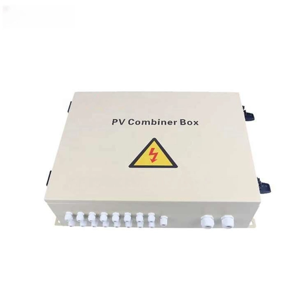
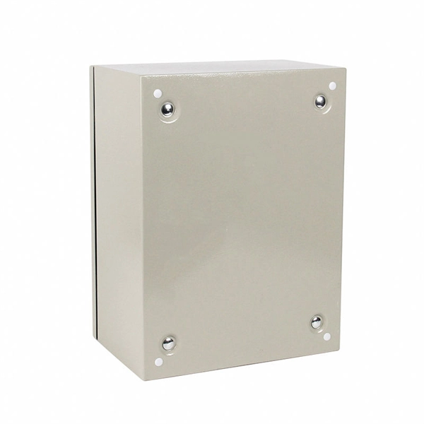
This AutoCAD DWG file includes a complete Single Line Diagram (SLD) of a Distribution Board, showing circuit breakers, wiring connections, and load distribution for lighting, power, and mechanical systems. An electrical panel box, also known as a breaker box or a distribution board, is a crucial component of any electrical system. It serves as a central hub for distributing electricity throughout a building, ensuring that power is delivered safely and efficiently to all the required locations. And all the switching and protective devices are installed in the. A distribution box is a key part of electrical systems in buildings. Inside, you'll find parts like circuit breakers and fuses that protect the system from problems like overloads and short circuits. Today, electrical systems are essential for homes and industries. Electrical Distribution board is used for controlling of utilization of power in the end point like as lighting circuit, power circuit and other equipment like as TV, fridge and airconditioning. The incomer supply is received from distribution panel. In this board, balance load is distributed as.
[PDF]
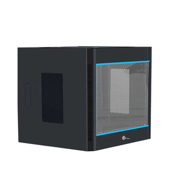
In this video, we'll walk you through the step-by-step process of installing a distribution board (also known as a breaker panel) safely and efficiently. Choose the right box based on environment (indoor/outdoor), load capacity, and durability. Check for proper IP/NEMA ratings and material quality. It has three categories: residential, commercial and industrial electrical distribution boxes, all of which play important roles in their respective electrical. A cable distribution box is an electrical device used to collect, distribute, and protect electrical power. It is usually equipped with circuit breakers, fuses, terminal connectors, and other components. It is mainly used to isolate fault circuits, prevent overload, and ensure the safe operation of. A residential breaker box, or load center, is the heart of a home's electrical distribution system. This panel routes power from the utility service to every circuit while housing circuit breakers that provide overcurrent protection. Whether you're a beginner or an experienced DIYer, this tutorial will cover everything from selecting the right distribution board to wiring and. When your circuit breaker trips, it's convenient to have your electrical panel in an easy-to-reach location. But you must follow electrical panel location rules when choosing a spot—even if incorporating them into interior design is challenging—and you can't cover them without breaking fire codes.
[PDF]
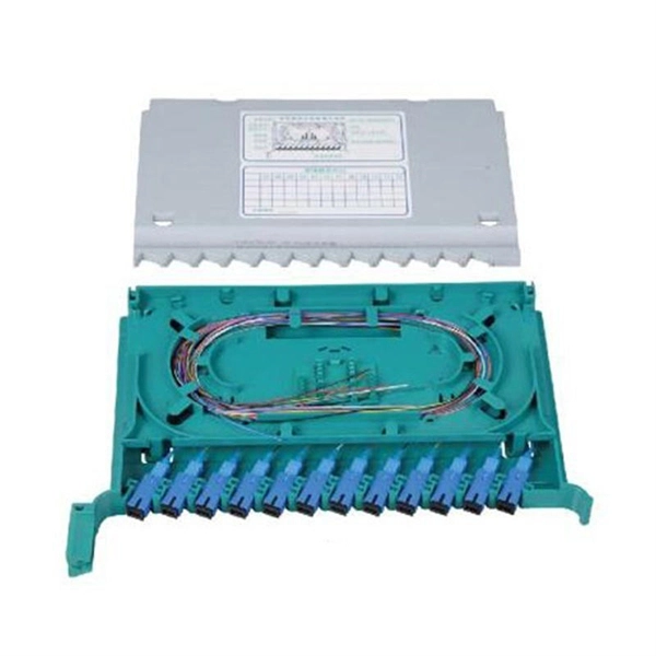
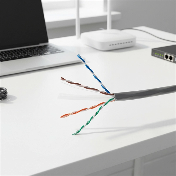
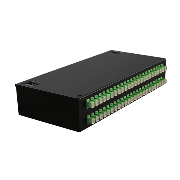
To check a fiber connection, connect a jumper to the optical source port and the other end to an optical meter. Press the “test” or “signal” button to send a signal from the source to the meter. In this blog, we'll explore different methods, including using a flashlight, advanced tools like Fluke testers, and more cost-effective options for testing fiber optics. First, we'll show you the. This guide will walk you through diagnosing and resolving common fiber network issues efficiently. Why Do Fiber Networks Fail? Despite their robustness, fiber networks can fail due to: Physical Damage : Cuts, bends, or contamination in fiber cables or connectors. Below is an in-depth guide on how to assess the health and performance of a fiber optic connection: Before relying on technical tools, start. While there are many different fiber optic cable tests, the most common version is an insertion loss test, also known as an attenuation, jumper, or connectivity test. This test requires a special testing kit and protective eyewear, but it will help you diagnose problems with the cable's. We'll explain why it's vital to test fiber optic cables, the three most popular methods, and when you should use them. Related: Fiber Optic Connectors – Identification Guide Regularly testing fiber optic cables helps minimize network downtime, lengthens the network's longevity, reduces maintenance.
[PDF]
An OTDR is a powerful tool that helps technicians and engineers assess the health of fiber optic cables. OTDRs inject high-powered light pulses into the fiber using specialized laser diodes. As these light pul.
[PDF]
Explore our full range of inspection tools, OTDRs, power meters, FTTx diagnostics, and software designed for fast, reliable network deployment and maintenance. Pocket-sized and performance packed, AFL optical time domain reflectometers (OTDRs) and fault locators certify new fiber installations and locate faults in deployed fiber optic networks. Easy operation makes even a novice a testing expert. Robust Cloud- and PC-based reporting tools that provide. Do you also provide customisation in the market study? Yes, we provide customisation as per your requirements. To learn more, feel free to contact us on sales@6wresearch. com Any Query? Click Here. A Two-Way Optical Loss Tester (OLTS) that's perfect for medium to ultra high fiber count loss, length and optical return loss testing applications on multimode fiber at 850 / 1330nm. A pair of these compact instruments set new standards of productivity, accuracy and ease of use. A multimode APC. O/E LAND, a provider of optical measurement, switching, and infrared photonic instruments, is featured on GoPhotonics for its diverse portfolio of optical spectrum analyzers, fiber optic switches, circulators, detectors, and power meters designed for advanced photonic and sensing systems. Used together with GAO's C0220003 handheld optical light source, it offers a quick and accurate testing solution for both single and multi-mode fibers. The VIAVI OMK-3xV2 optical test kits are a range of pocket-sized and rugged instruments for installi.
[PDF]
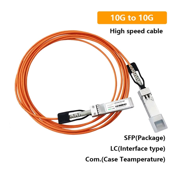
A common test setup to evaluate Stressed Receiver Sensitivity involves measuring the Optical Modulation Amplitude (OMA) using a square wave, per the standard guidelines. Receiver sensitivity stands as a critical parameter impacting an optical transceiver's functionality. It denotes a module's capability to function in challenging environments and aids network operators in determining the system's maximum reach or link margin. These metrics provide insights into how well your transceivers perform under different conditions, ensuring seamless data transmission. Optical. Whether you're a network engineer validating new inventory or an integrator preparing for deployment, knowing how to test optical transceiver modules can save time, reduce failures, and ensure SLA compliance. Unchecked optical modules can cause: Testing ensures compliance with IEEE 802. 3 and MSA. In optical communication systems, sensitivity is a measure of how weak an input signal can get before the bit-error ratio (BER) exceeds some specified number. The standards body governing the application sets this specified BER. For example, SONET specifies that the BER must be 10 -10 or better. Why Fiber Optic Transceiver Testing is Important? Identify faults and failures: Transceiver testing helps in identifying any faults.
[PDF]
A spectrophotometer is a piece of spectroscopy equipment measures the amount of light absorbed by a sample. This measurement can be useful in many research applications: To identify materials by mapping molecular absorption profiles. To work out solute concentrations in solutions. Specifically, a UV-Visible Spectrometer measures the absorption or transmission of light in the ultraviolet (UV) and visible (Vis) regions of the electromagnetic. A spectrometer is a scientific instrument that analyzes light to reveal information about materials. It functions by separating light into its constituent wavelengths, much like a prism splits sunlight into a rainbow. This analytical capability makes spectrometers valuable tools across many fields. Spectrophotometry is an experimental technique that is used to measure the concentration of solutes in a specific solution by calculating the amount of light absorbed by those solutes. It is widely used in laboratories to analyze various substances, from liquids to gases. Here's a step-by-step guide on how to use a spectrophotometer. When you use spectrophotometry, you gain skills that help in many science fields. This guide makes spectroscopy simple by showing you how to use teaching tools and real experiments. The basic principle is that each compound absorbs or transmits light over a certain range of wavelength. This measurement can.
[PDF]
The following tutorial shows how to wire 120V single phase breaker box installation in home. 120V single phase circuits are generally used in home wiring for lighting circuits and outlet receptacles. To do.
[PDF]