To connect a fiber, align the optical connector with the optical port and gently insert the optical fiber into the port. A fiber adapter (also called a flange) is a fiber connection component. An active optical cable (AOC) is a fixed-length optical fiber with optical modules at both ends. It can be directly connected to an optical port on a device. Table 10-3 lists the models and attributes of. Optical modules are widely used in switches, network interface cards (NICs), routers, and other communication devices. During use, reading optical module information helps understand its real-time operating status, enabling faster troubleshooting of link abnormalities. Solution: To solve this problem, you can follow these steps: Check if the fiber and optical modules are compatible. Perform a. All other trademarks and trade names mentioned in this document are the property of their respective holders. The purchased products, services and features are stipulated by the contract made between Huawei and the customer. Major causes of the interface physically down event include hardware and software failures. Hardware failures: include hardware. Step 1: Antistatic strap must be worn to prevent static damage. Step 2: Take out the optical module, ring and label up, the gold finger is facing down, Note that the right and the negative can not be reversed.
[PDF]
o In optical modules, "core" refers to the light-transmitting channel in the fiber. A 1-core module uses a single fiber core for data transmission, while a 2-core module uses two cores. o Think of a highway. A 1-core fiber is like a single-lane road—only one car (or. The secret lies in fiber optic technology, and understanding the basics—1-core, 2-core, Single Mode (SM), and Multi-mode (MM)—is key to mastering this field. Let's break down these terms in simple, clear language with practical examples. Definitions · 1-core vs. A. SFP (Small Form-factor Pluggable) is a compact, hot-pluggable network interface module used to connect network devices (switches, routers, firewalls) to fiber optic or copper cables. Think of it as the “translator” for your network equipment, converting electrical signals into optical signals. An optical transceiver is a modular device that serves as both a transmitter and a receiver (hence the name). In fiber optics, the data is sent in the form of light pulses or signals at high speeds and over long distances. The fiber optic transceivers convert the electrical input received from.
[PDF]
Frequent status changes from up to down or vice versa in the ports logged by the switch port syslog indicates a port flap. On a big industrial plant we've replaced an old HP switch with a brand new couple of C2960x switches in stack configuration and ever since then, every 6/8 hours or so, the two fiber optics links of switch #2 go down at once. These are connected to a ring of 3 similar other access switches, that. EX4650 2-switch virtual chassis, running version 19. 2, optic p/n 740-031981 (SFP+-10G-LR) is plugged into port xe-0/0/10 and connected to an ISP via single mode fiber. Nothing special is configured on the port, it is running at 10G speed, show interfaces diagnostics optics shows that it's. This article describes steps to diagnose the Continuous port flapping on a FortiSwitch. Verify Cable Connection: Ensure the cable is properly connected between the switch port and the end device. Run the command below on FortiSwitch multiple times and check the. Real head scratcher this morning that I'm hoping someone can help me with! The port on our core switch (HP A5500) that our Smoothwall box is connected to keeps going up and down. Port flapping, also known as link flapping, causes a switch port's state to fluctuate between up and down within concise periods of time. This instability caused by flapping ports affects network connectivity. Port flapping is a common network issue that can disrupt communication between devices and degrade overall network performance.
[PDF]
We demonstrated a fast polarization-insensitive optical switch on the 220-nm SOI platform with an insertion loss of 0. 79 dB and a response time of 52. 0 ns for TE0/TM0 mode at the 1550 nm wavelength. GLSUN's nanosecond optical switches are a class of high-speed optical devices capable of switching optical signals in the nanosecond range. 2 dB), fastest switching speed (10 ns), broadest wavelength range (300–2400 nm), widest fiber compatibility, highest optical power handling (50 W), and space-qualified reliability. Backed by over 25 years of. The nano-second speed PLZT optical switch subsystem is equipped with a MZ type PLZT switch module designed for 1550 nm wavelength range, single mode fiber ports, and a TTL controllable high-speed driver. Enclosure case mount option is available. *Dual switch: Two switches are integrated on a silgle. A family of low loss and high-speed switches. All specifications subject to change without notice. Need More Information?. W. Zhou, "Polarization-Insensitive Silicon Optical Switch with Nanosecond Switching Speed," in CLEO 2025, Technical Digest Series (Optica Publishing Group, 2025), paper AA120_5. The fact that optical DCNs rely on optical circuits of microsecond-scale durations makes nanosecond-precision time synchronization essential for the correct functi ning of routing on the network fabric. However, current studies on optical DCNs neglect the.
[PDF]
The operating principle of an OCS is similar to telephone circuit switching. When two ports need to communicate, the controller configures a path in the optical switch matrix, using optical components to route the optical signal from one fiber to another, forming an independent. Optical switching represents a fundamental technological evolution, shifting data routing from the domain of electrons to the realm of photons, or light. This transition allows data to remain in its native optical form as it travels through fiber optic networks, eliminating the need for. Optical switches are devices that route light signals from one path to another without converting them into electrical signals first. They're a core component in fiber-optic networks, where data travels as pulses of light through glass fibers. Every time that light needs to change direction or jump. Optical switches, a key component in modern network infrastructure, are devices used in optical fiber networks for signal management. Unlike traditional electrical switches, which transmit data as electrical signals, optical switches handle data transmission in the form of light. These devices play a critical role in modern optical networks by enabling dynamic reconfiguration, wavelength routing, and protection switching. In this article, we will explore the fundamentals of optical switches, their types, and their applications in various fields. An optical switch is a.
[PDF]

The short answer is no - RJ45 connectors are designed for electrical Ethernet signals, while fiber optics transmit light pulses through glass or plastic. However, modern networks often combine both technologies. A combo port, also known as an optoelectronic multiplexing interface, is a photoelectric composite port with two kinds of Ethernet interfaces (RJ45 port and SFP port) on an Ethernet switch. In other words, it is a compound port that can support two different physical layers and share the same. Optical ports on switches typically require the insertion of optical modules for data transmission over fiber optics. However, these two different physical ports can not be used at the same time. If you wake up the RJ45 port, the corresponding SFP port will. Ensuring seamless interoperability and compatibility between optical transceiver modules and network devices is crucial for maximizing network performance, reducing downtime, and controlling operational costs. This guide dives deep into the core aspects of optical transceiver compatibility, common. SFP (Small Form-factor Pluggable) is a compact, hot-pluggable network interface module used to connect network devices (switches, routers, firewalls) to fiber optic or copper cables. Think of it as the “translator” for your network equipment, converting electrical signals into optical signals.
[PDF]
The BDCOM S5828 employs a cutting-edge hardware architectural design to deliver the best switching performance and a wealth of data center service capabilities available in the market. Bangladesh - Shop for Best Online at Daraz. bd Wide Variety of sfp network switch. Great Prices, Even Better Service. Modular All Brands BDCOM BDCOM RX1550 1. Image may differ with actual product's layout, color, size & dimension. No claim will be accepted for image mismatch. Product data used in this website is based solely on its manufacturer provided information, authenticity and. This Small Form-Factor Pluggable (SFP) module is a compact, pluggable transceiver module that is used in your networking and telecommunication system. It is mainly used for fast data transfer over Ethernet, fiber optic or copper cables, and is also suitable for installation in switches, routers. The BDCOM S5800 series switch is a new generation of high-performance data center all-Gigabit TOR switch launched by Shanghai BDCOM Co. for high-performance cloud computing, data centers, and high-end campus networks.
[PDF]
Compare products based on your own technical specification criteria. How does our search work? With MEET OPTICS search you get direct access to our database of thousands of optical components from providers worldwide. Prices and product specifications directly listed from optical component. Use this fiber optics buying guide to compare major types, define selection criteria, and find suppliers: Click on a logo to get to the details of that supplier's offer. Our list of suppliers for that category contains 230 suppliers. Understand the Technical Background To support your technical. Explore 9 top manufacturers and suppliers of Fiber Optic Sheathing in our comprehensive photonics buyers' guide. Nextrom is a leading global supplier of production technologies for optical fibers and fiber optic cables. This guide outlines typical cost ranges and the main drivers behind pricing to help formulate a budget and estimate expenses. Cost factors include material. Looking for one of the fiber optics industry leaders? Look no further, Fiber Instrument Sales inventories over $10 million in fiber optic merchandise. Most of it ships the same or next day. As always, in stock and ready to go. Visit our comprehensive site. Sign up for our newsletter to receive specials and up to date product news and releases. We offer fiber optic materials from Test Equipment, Bulk Cable and Fusion Splicers to Tools, Patch Cables and Consumables.
[PDF]
An optical module is a typically hot-pluggable optical transceiver used in high-bandwidth data communications applications. Optical modules typically have an electrical interface on the side that connects to the inside of the system and an optical interface on the side that connects to the outside world through a fiber optic cable. The form factor and electrical interface are often specified by an int. Electrical Interface TypesThere have been multiple variants of the electrical interface of optical modules that have been used over the years. The earliest forms of optical modules had an analog electrical interface. In the transmit dir. Many different forms of optical modulation and multiplexing have been employed in optical modules. The most common modulation technique historically has been or NRZ.
[PDF]
Yes, fiber cables can be bent during installation, which proves particularly useful when you pull cables into position rather than using blown installation methods. Blown fiber installation uses air pressure to propel cables through conduits, minimizing bending stresses. Fiber optic cables are designed to withstand some bending, but excessive bends can physically damage the glass fiber or cause significant signal loss. That's why every fiber cable has a minimum bend radius specification provided by the manufacturer. The minimum bend radius defines the smallest. All fiber optic cables have specifications that must not be exceeded during installation to prevent irreparable damage to the cable. Installers must understand these specifications and know how to install cables without. The bend radius of fiber cables is critical for maintaining high performance and longevity. A practical single-mode fiber option for compact routing, dense fiber management, FTTH access, and reel-based systems such as drone fiber and FPV fiber tether where bend-loss control matters in real installation and maintenance conditions. The tighter the bend, the smaller the radius. The minimum bend. Astel 4 Core Siamese model has 2 x 2 Fiber cables joined in the center by steel messenger. Its main advanctage is that a single cable can be used for 2 independent telecom operators. The optical fiber is made of high pure silica and.
[PDF]
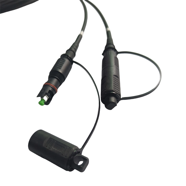
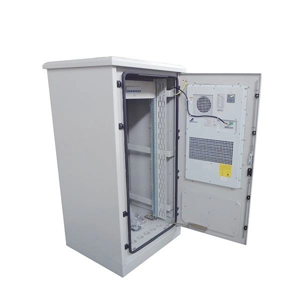
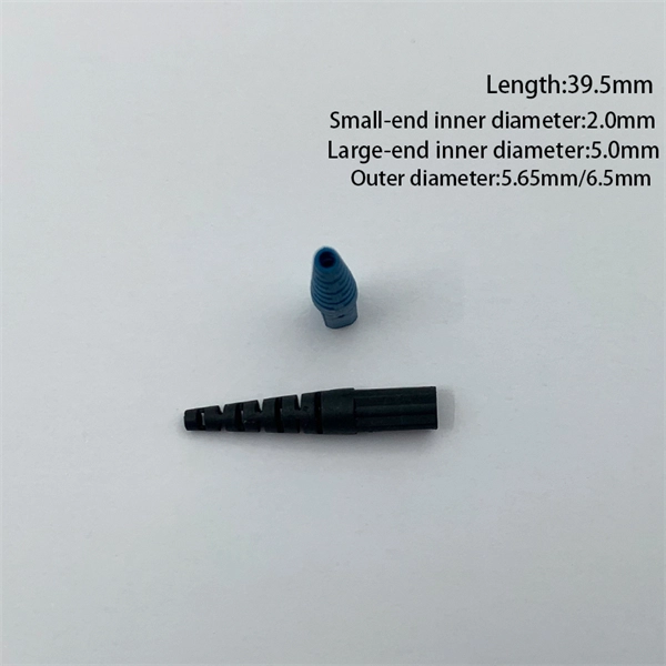
Through the adapter in the distribution box, the optical signal is led out by the optical jumper to realize the optical wiring function. An optical cable consists of three primary parts: the core, the cladding, and the protective sheath. The core is at the center of the optical cable and serves as the pathway for transmitting light signals. Surrounding the core is the cladding, which has a lower refractive index than the core. In the complex architecture of fiber optic networks, the Optical Distribution Frame (ODF) serves as the linchpin for organizing, protecting, and distributing optical signals. Whether in data centers, telecom central offices, or enterprise network rooms, ODFs enable efficient fiber management. The optical fiber distribution box is to protect the connection point where the optical cable is connected to the user end, so that the optical cable access point is stable, dustproof and waterproof. What is a fiber distribution box? 2. The. A fiber distribution box (FDB) functions as a central hub in fiber optic networks where the main cable is split into multiple individual fibers for distribution to end users. These boxes protect sensitive fiber connections from environmental factors while providing an organized framework for.
[PDF]
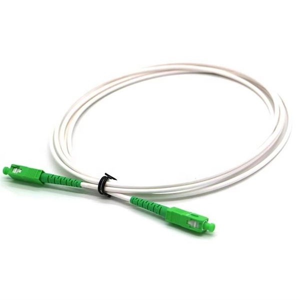
A PLC splitter is a passive optical device that divides one incoming optical signal from an input fiber into multiple output signals across several output fibers. PLC splitters utilize a planar lightwave circuit chip made of silica glass waveguides to distribute the optical power. PLC optical splitters (planar waveguide optical splitter) is a key component in optical fiber communication networks and is widely used in optical fiber distribution systems such as FTTH (fiber to the home) and PON (passive optical network). This passive yet sophisticated device utilizes integrated optics technology to split a single input signal into multiple. PLC splitter, also called Planar Waveguide Circuit splitter, is a device used to divide one or two light beams into multiple light beams uniformly or combine multiple light beams to one or two light beams. This helps share signals in fiber optic networks. Pick the split ratio that matches what you need. Lower ratios work for fewer users. Choose the connector type like SC, LC, or FC.
[PDF]
This review provides a comprehensive assessment of recent advances in polymer photonic sensing technologies, focusing on material systems, fabrication techniques, device architectures, and application domains. Waveguide technology represents a fundamental approach to controlling and directing electromagnetic waves, particularly in optical and microwave applications. This technology has evolved from basic optical fiber principles to sophisticated integrated photonic systems that enable high-speed data. Optical waveguides can be described as transparent structures which are more or less put onto solid carriers. In principle, they function just like fibers and are also described by the same parameters. However, there are also some fundamental differences: Waveguides are not produced ready-made by. The MZI structure consists of a polymer waveguide arm and a doped silica waveguide arm. Due to the opposite thermal optical coefficients of polymers and silica, the hybrid integrated MZI structure enhances the temperature sensing characteristics. The direct coupling method and side coupling method. Polymer-based photonic sensors are emerging as cost-effective, scalable alternatives to conventional silicon and glass photonic platforms, offering unique advantages in flexibility, functionality, and manufacturability. The design of the presented planar waveguides was realized on the bases of modified dispersion equation and was.
[PDF]
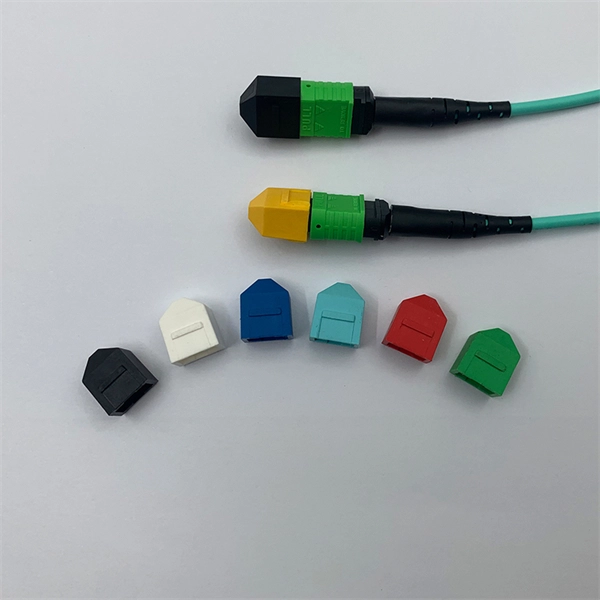
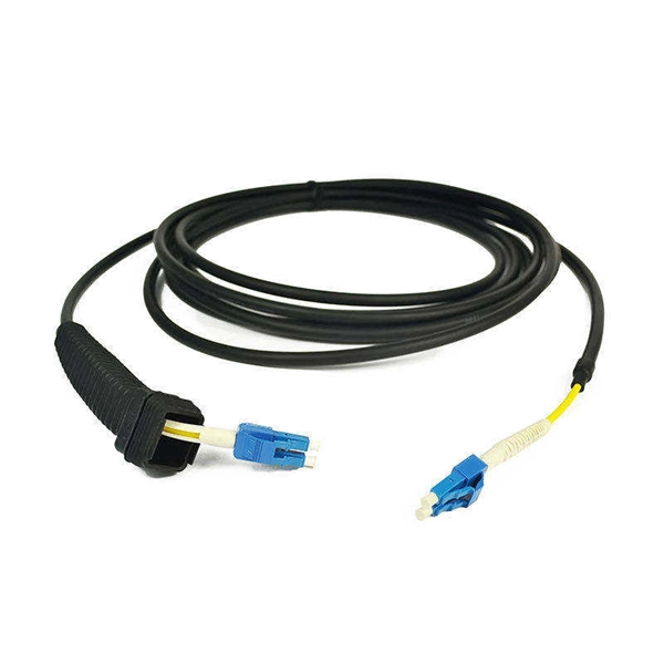
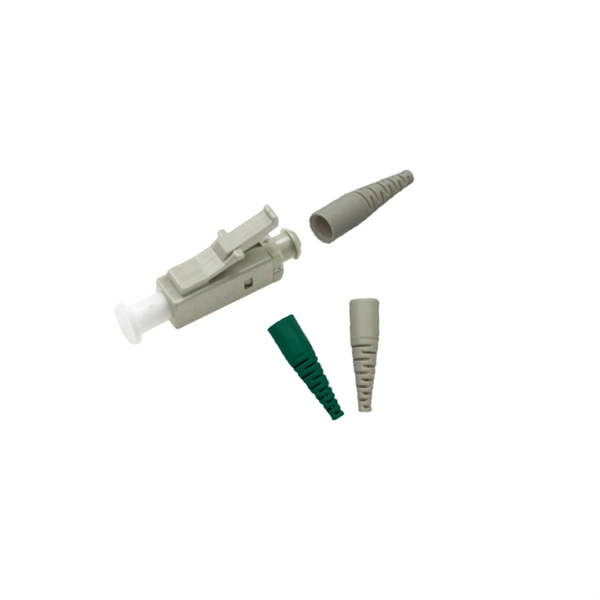
Fiber optic pigtails have only one terminated connector on one side but bare fibers on another side. Executive Summary: A fiber optic pigtail is one of the most commonly specified yet least understood components in structured cabling. Get the wrong connector type, the wrong polish, or skip proper fusion splicing technique—and you're looking at elevated signal loss, increased back reflection, and a. When you build or upgrade a fiber network, the same four words pop up everywhere— fiber optic (bare fiber), pigtail, patch cord, optical cable. They're related, but they are not interchangeable. Mixing them up drives costs higher, increases loss, and slows your rollout. The good news? Once you nail. A fiber pigtail is typically a fiber optic cable with one end factory pre-terminated fiber connector and the other exposed fiber. It is usually suitable for field termination using a mechanical or fusion splicer. It primarily finds its application in terminating optical fibers on networking equipment, including patch panels, distribution frames, or optical transceivers. The bare end is normally.
[PDF]
Below is a detailed comparison table of typical optical module speeds ranging from 1G to 400G, highlighting wavelength, reach, power budget, connector type, data rate, and operating temperature. Optical modules, also known as transceivers, convert electrical signals to optical signals and vice versa. They come in multiple speed grades standardized by IEEE 802. 3, enabling data rates from 1 Gbps (Gigabit Ethernet) up to 400 Gbps (400G Ethernet). The choice of module speed directly impacts. We provide an industrial-grade reference framework, complying with the latest MSA (Multi-Source Agreement) updates, including SFF-8679 Rev 1. 4 (Jan 2025), to help you design robust, scalable optical fabrics. The Master Reference Matrix: SFP vs. QSFP Standards (2025 Edition) This table. Upgrade to 100G or 400G optics and save. Cisco Transceiver Modules - Learn product details such as features and benefits, as well as hardware and software specifications. How does our search work? With MEET OPTICS search you get direct access to our database of thousands of optical components from providers worldwide. com, we specialize in Cisco-compatible and NS Comm transceivers, offering enterprise customers tested, certified. SFP (Small Form-factor Pluggable) is a compact, hot-pluggable network interface module used to connect network devices (switches, routers, firewalls) to fiber optic or copper cables.
[PDF]