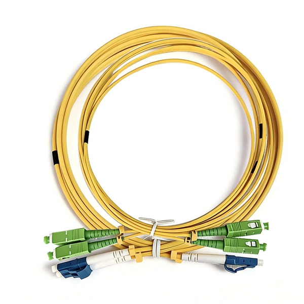
According to the IBDN standard, we generally recommend using 12 cores for the communication room in each building, and 24 cores for the building room. Of course, this is a general situation, and specific w.
[PDF]
Connect the Ethernet cables: Connect one end of an Ethernet cable to the PoE switch's uplink port, and the other end to the network router or modem. Then, connect the devices that require power to the PoE ports on the switch using Ethernet cables. A Power over Ethernet (PoE) switch is a device that enables the transmission of both power and data over a single Ethernet cable. This eliminates the need for separate power cables and allows for flexible placement of network devices in locations where power outlets may be limited or absent. In. The first thing you need to do is connect your switch to an electrical outlet so it is powered on. This means you can power devices such as wireless access points, IP cameras, and VoIP phones using the same cable that provides network connectivity. 3at (PoE+), and. One of the biggest advantages of copper twisted pair Ethernet cable (also called Category cable) is it's ability to perform two critical functions at the same time: When these functions are simultaneously performed, it is known as PoE or Power over Ethernet. It utilizes efficient low-voltage 43 to 57 VDC over twisted-pair network cabling, such as Category 6A, Category 6, and Category 5e. This means PoE can be installed without risk to.
[PDF]
A PoE Switch is a type of network switch that sends both data and electricity through one cable. This helps power devices like IP cameras or wireless access points without needing extra power cords. It streamlines installation, enhances cable management, and lowers overall costs. What is a PoE switch (Power over Ethernet switch)? What is PoE Switch? A PoE (Power over Ethernet) switch is a network switch that delivers both power and data through a single Ethernet cable to connected devices such as IP cameras, VoIP phones, wireless access points, and IoT devices. There are different PoE types, standards modes available. This article will focus on the differences between some of the PoE types and standards that are relevant to. A PoE Switch can provide data and power through one Ethernet cable. This can solve the clutter problem and remove a lot of headaches. Let's dive deep into the intricacies of PoE switches, their benefits, applications, and how integrating them with networking equipment from Router-switch.
[PDF]

The IEEE standard for the base PoE switches is 802. 3at for PoE+, and 802. PoE and PoE+ transmit power over two pairs of twisted-pair wires in their cables, while the PoE++ variants use four pairs of twisted-pair wires. The splitter is the silver and black box in the middle between the wiring junction box (left) and the access point (right). The PoE connection eliminates the need for a nearby power outlet. In another common configuration, the access point or other connected device includes internal PoE splitting. Power over Ethernet (PoE) switches combine data and power delivery into a single Ethernet cable, simplifying deployment of devices such as access points, IP cameras, VoIP phones, and IoT equipment. PoE does not reduce network speed, does not waste excessive power when proper cabling standards are. Therefore, everyone is concerned about whether PoE switches will affect speed. Key Benefits of Power over. PoE switches (Type 1) comply with the IEEE 802. 3af standard, which specifies the maximum power delivered over Ethernet cables.
[PDF]
PoE delivers 44-57v of DC power over unshielded twisted-pair wiring for terminals consuming up to 25 watts, depending on the version of the standard in use. Power over Ethernet (PoE) describes any of several standards or ad hoc systems that pass electric power along with data on twisted-pair Ethernet cabling. This allows a single cable to provide both a data connection and enough electricity to power networked devices such as wireless access points. Imagine powering your entire network infrastructure through the same cables that carry your data, eliminating the need for separate power supplies and electrical outlets near every device. This isn't a futuristic concept—it's the reality that power over Ethernet has made possible since 2003. While PoE doesn't add Ethernet data capabilities, it does offer expanded options for how and where Ethernet end devices can be. Power over Ethernet is a technology that allows IP telephones, wireless LAN Access Points, security network cameras and other IP-based terminals to receive power, in parallel to data, over the existing CAT-5 Ethernet infrastructure without the need to make any modifications. The simple nature eliminates the need for multiple power supplies, and allows connectivity to devices where power outlets are not available. Instead of running a separate power line to each device, PoE lets the Ethernet cable (usually a Cat5e or Cat6 cable) carry both the network connection and.
[PDF]
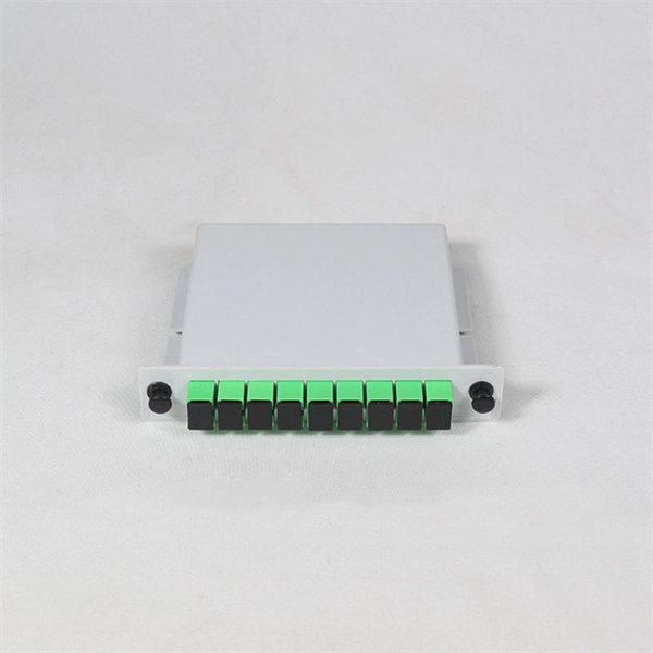
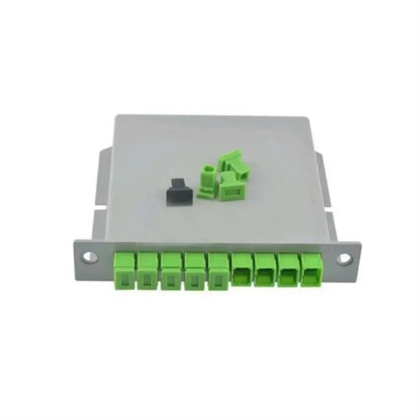
The 12-Core configuration of the MTP cable refers to the number of fibers within a single connector. This design allows for efficient data transmission and is particularly well-suited for high-density applications where space optimization is critical. According to the IBDN standard, we generally recommend using 12 cores for the communication room in each building, and 24 cores for the building room. Of course, this is a general situation, and specific words may consider according to the following criteria. Number of wiring points and switches. Optical fiber cables are used to transmit large amounts of data over long distances. In this article, we will discuss the differences between these two cables in terms of their. However, if there were no cores, fiber optic cables would be useless. The reason is that cores are basically hidden components located that receive the light signals. Don't worry, in this guide, we'll discuss in detail what the fiber optic core is and its role in data transmission. Moreover, we'll. Among the various types of fiber optic cables available, the 12 core fiber optic cable is a common choice for many applications due to its balance of capacity and flexibility. Made from either high-quality glass or plastic, the core plays a critical role in determining the cable's performance. Multimode fiber optic cables can carry multiple light modes or signals, making them ideal for.
[PDF]
To connect a fiber, align the optical connector with the optical port and gently insert the optical fiber into the port. A fiber adapter (also called a flange) is a fiber connection component. An active optical cable (AOC) is a fixed-length optical fiber with optical modules at both ends. It can be directly connected to an optical port on a device. Table 10-3 lists the models and attributes of. Optical modules are widely used in switches, network interface cards (NICs), routers, and other communication devices. During use, reading optical module information helps understand its real-time operating status, enabling faster troubleshooting of link abnormalities. Solution: To solve this problem, you can follow these steps: Check if the fiber and optical modules are compatible. Perform a. All other trademarks and trade names mentioned in this document are the property of their respective holders. The purchased products, services and features are stipulated by the contract made between Huawei and the customer. Major causes of the interface physically down event include hardware and software failures. Hardware failures: include hardware. Step 1: Antistatic strap must be worn to prevent static damage. Step 2: Take out the optical module, ring and label up, the gold finger is facing down, Note that the right and the negative can not be reversed.
[PDF]
The operating principle of an OCS is similar to telephone circuit switching. When two ports need to communicate, the controller configures a path in the optical switch matrix, using optical components to route the optical signal from one fiber to another, forming an independent. Optical switching represents a fundamental technological evolution, shifting data routing from the domain of electrons to the realm of photons, or light. This transition allows data to remain in its native optical form as it travels through fiber optic networks, eliminating the need for. Optical switches are devices that route light signals from one path to another without converting them into electrical signals first. They're a core component in fiber-optic networks, where data travels as pulses of light through glass fibers. Every time that light needs to change direction or jump. Optical switches, a key component in modern network infrastructure, are devices used in optical fiber networks for signal management. Unlike traditional electrical switches, which transmit data as electrical signals, optical switches handle data transmission in the form of light. These devices play a critical role in modern optical networks by enabling dynamic reconfiguration, wavelength routing, and protection switching. In this article, we will explore the fundamentals of optical switches, their types, and their applications in various fields. An optical switch is a.
[PDF]
Factory terminated pigtails can easily be fusion or mechanically spliced to an existing fiber line. Custom lengths, connector combinations and. This 12-fiber optic pigtail is designed for efficient fusion splicing in structured cabling systems. It supports data centers, CATV, PON, WDM/DWDM multiplexing, FTTH, and voice services in ATM and SONET networks. With OS2 bend-insensitive fiber, it minimizes attenuation caused by bends or twists. ( Order Today, Ship before 05/01/2026 ) We supply LC/APC Single mode 12 Pack Multi Color Fiber Optic Pigtails with competitive price. We supply quality LC/APC Single mode Fiber Optic Pigtails are 12 packs that are 3 meters long with 900um outter jacket. Ideal for fusion splicing. We also offer. New to ADI? Become a Customer Please sign in to view pricing, availability, and to add to cart. Country of Origin: United States. Featuring LC style connectors, these pigtails are sold in a convenient 12 pack. FS 12 fibers pigtails with LC SC connectors feature color-coded or bunch design for various fiber splicing applications. 100% end-face, 3D interferometer, IL & RL tested. The LC APC 12 core bundle fiber optic pigtail consists of twelve individual fiber optic pigtails, each terminated with an LC APC connector on one end.
[PDF]
Most modern fiber-enabled network switches require an SFP transceiver module featuring a duplex (two strand) multimode OM3 or duplex single mode OS2 connection with LC connectors. Direct attach cables with pre-terminated SFP connections may also be used. Download the Application. CONFIGURING THE SWITCH IN DESIGO CC/CERBERUS DMS. CYBERSECURITY DISCLAIMER. 44. This tutorial will explain the steps required to configure fiber optics on a Cisco switch and ensure proper connectivity in your network. This chapter includes the following sections: •Information About Fibre Channel Interfaces, page 1-1 •Configuring Fibre Channel Interfaces, page 1-8 •Configuring Global Attributes for. : 192. 0 De livery of solutions fulfilling the Customers' multitude o. This document is intended to serve as a guide for architecting and deploying fiber optic networks in a customer environment. This installation planning guide describes some basic fundamentals of fiber optic technology, considerations for deployment, and basic testing and troubleshooting procedures. Fiber optic cabling is increasingly used to connect network switches and other datacom equipment, especially in long-distance and mission-critical applications. Fiber provides: Increased internet signal bandwidth.
[PDF]
Cisco announces the end-of-sale and end-of-life dates for the Cisco Catalyst 1000 Series Switches. The last day to order the affected product (s) is April 30, 2025. Tax included. This item is a deferred, subscription, or recurring purchase. By continuing, I agree to the and authorize you to charge my payment method at the prices, frequency and dates listed on this page until my order is fulfilled or I cancel, if permitted. Customers with active service contracts will continue to receive support from the Cisco Technical Assistance Center (TAC) as shown in. Intuitive software interface for effortless network configuration and monitoring. 8 x 1G ports Energy efficient 2 x 10G ports The NETGEAR 10-Port Gigabit/10G Ethernet Plus Switch (GS110EMX) is a versatile and efficient networking solution featuring 8 x 1G and 2 x 10G ports, designed for seamless. Cash On Delivery. Delivery All Over Lebanon. A 24-port, Layer 3 switch capable of high-power PoE++ output. Flexible 10 Gigabit connectivity for SME and SMB environments. Packet Forwarding Rate Buy online D-Link 24-Port Gigabit Stackable Smart Managed Switch with 10G Uplinks |DGS-1510-28XMP at ayoubcomputers. AYOUB. Discover the TP-Link Switches collection, providing efficient networking solutions designed to enhance connectivity and streamline your network infrastructure. These switches deliver reliable performance and advanced features, making them ideal.
[PDF]
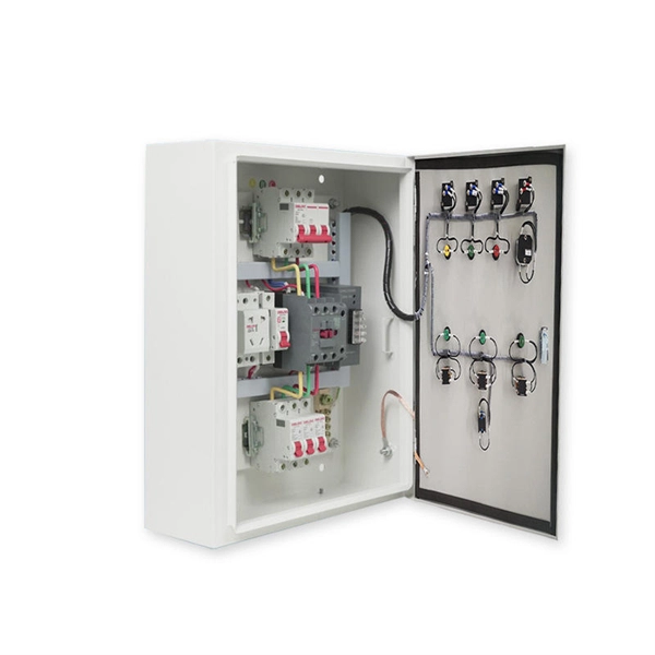
Customise your electrical equipment in a few clicks from our online configurator and generate a quote to make your project a reality. We create high-end electrical equipment from raw material. Made in France since 1976. Discover all the finishes of our collections in 3D and get your prescription. IGOTO supplies European light switches and wall socket to Fortune Global 500 brands, delivering certified, reliable solutions trusted across residential, commercial, and OEM markets. Explore our best-selling European light switches and electric plug sockets in Europe – modern design, multi-standard. With over 55,000 flex7 Lighting Distribution Boxes installed every year there's got to be a reason they're such a popular choice. Every product in our vast range is carefully designed to ensure that it provides the best experience for the user. Our Lighting Distribution Boxes are by no means an. European, British, International Flush Mount Plastic Electrical Wall Box, 35mm deep. Flush Mounts Single Outlets & Switches in Sheet Rock Walls or 1/4"-7/8" Thick Panels. The range of applications extends from pure energy distribution in buildings to building automation and through to industrial plants. SMART DISTRIBUTION BOXES FOR FLEXIBLE BUILDINGS. These switches are designed to meet strict safety standards, including compliance with IEC (International Electrotechnical Commission) regulations and CE.
[PDF]
In this video, we'll guide you through the process of configuring a Huawei Switch for your network. Whether you're setting up a new switch or optimizing your existing network infrastructure, this step-by-step tutorial will help you get the job done efficiently. This document provides campus networks typical configuration examples and feature typical configuration examples. "Campus Networks Typical Configuration Examples" provides typical campus network networking modes and a variety of deployment examples. This document is for switches running V200R003C00 and later. In this video, we'll guide you. Saving Configuration: Save changes to make the configuration permanent: Checking Settings: Use commands like display user-interface console 0 to verify correct configuration. Exiting the Device: Log out of the device after completing the configuration. Enabling Telnet Service and Granting Access on. The Combo interface, also known as the optical-electrical multiplexing interface, consists of two Ethernet ports (one optical and one electrical) on the device panel, and there is only one forwarding interface inside the device.
[PDF]
Check the steps ① whether the user network card is disabled, ② check whether the network cable is normal with a network cable tester, ③ replace the optical modem LAN port or other ports of the router and switch to test whether normal. Fiber optic networks are celebrated for their speed and reliability, but even the best systems can encounter problems. When issues like signal loss, slow speeds, or intermittent connectivity arise, systematic troubleshooting is key. This guide will walk you through diagnosing and resolving common. We have a fibre run, SM, 650 meters, with Level1 dumb switches at each end, I get Link lights at both ends, but there's no network traffic. Switch A is on the router end, devices connected to this switch get DHCP leases and can browse the internet without issue. These high-speed, high-capacity communication networks are increasingly replacing copper cables, offering superior performance and. However, even the most advanced fiber-optic networks can encounter issues that disrupt performance. This comprehensive guide delves into the most common FTTH problems faced by users, providing detailed troubleshooting steps and real-world solutions. Whether you're a network engineer, IT manager, or service provider, understanding these challenges and how to address them is critical for maintaining high-performance, reliable.
[PDF]
This document provides instructions on configuring static LACP mode on a Huawei switch: create an Eth-Trunk interface, add GigabitEthernet ports as members, set the LACP priority to determine active/backup interfaces, and verify the configuration. This document provides campus networks typical configuration examples and feature typical configuration examples. "Campus Networks Typical Configuration Examples" provides typical campus network networking modes and a variety of deployment examples. The same configuration is required on the peer. This chapter describes how to configure link aggregation. Link aggregation bundles multiple Ethernet links into a logical link to increase bandwidth, improve reliability, as well as load balance traffic. Maintaining link aggregation includes monitoring the link aggregation running status and. In this comprehensive video, we delve into the intricacies of Link Aggregation Control Protocol (LACP) on Huawei switches. LACP plays a vital role in enhancing network performance, providing increased bandwidth, and ensuring high availability for critical applications. more In this comprehensive. Aggregation and access devices downstream to the core layer can automatically go online through Zero Touch Provisioning (ZTP). This section describes three automatic deployment modes, which can be selected based on the site requirements. Import information using the network plan template.
[PDF]