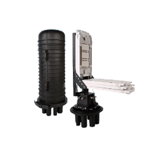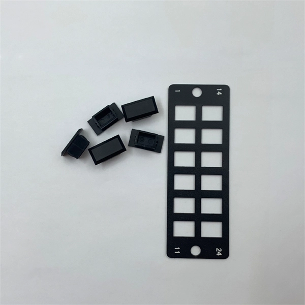
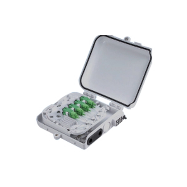
A splice box (also known as splice distributor) is a housing in which fiber optic cables begin or end. Fiber optics are fanned out in splice boxes that are situated at the end of fiber optic transmission paths. It typically consists of two parts: an outer housing and an internal structure. The main components of a splice box are the splice cassette that picks up the fibers and. The fiber optic dome splice closure is well-suited for splicing, distributing variable optical cables, and splitting. The solid box shell and the main structure are built to withstand harsh environments. The dome closure also protects fiber optic cables from vibration, impact, stretching, twisting. Home » Professional Insights » Fiber Optic Splice Closure: A Complete Guide to Types, Structure, Applications, and Selection In real fiber optic networks, cables are rarely installed as one continuous, uninterrupted length. Along transmission routes—whether in access networks, metro networks, or. Big space for managing pigtails or splitters. The 12 Port Fiber Distribution Box can connect up to 2 optical cables, providing space for distributors and 12 fuses. It is equipped with 12 SC adapters and can work in outdoor environments. Data communication networks. Horizontal fiber optic splice closures, also known as optical cable splice boxes, play an important role in the communications industry. It is a must-have device in the construction of optical cable line projects.
[PDF]
View or download our complete Fiber Optic Cable Catalogue with detailed specifications, certifications, and technical information. RHINO Cable is one of the leading Power and Communication cables suppliers in Ethiopia with more than 10 years of experience. Explore our comprehensive range of high-quality electrical, telecom, and fiber optic cables. Our product catalogue features detailed specifications and images to help you find the right solution for your project needs. BMET Energy Telecom Industry and Trade PLC” is the biggest capacity electrical. The Ethiopia Fiber Optic Cable Market is poised for steady growth rate improvements from 2025 to 2029. 41% in 2025, the growth rate steadily ascends to 16. Manufacturing excellence with 700,000,000. General Symmetric cable pairs Land coaxial cable pairs Submarine cables Free space optical systems G. 649 Optical fibre cables G. 659 Characteristics of optical components and subsystems Characteristics of optical systems G. 679. In Ethiopia, Huawei unveiled its brand-new OptiXtremeTM 400G DR4 series of fibre optic cables. The cables come in a range of lengths and configurations, and they can transport data at rates of up to 400 Gbps. In. Tailor every aspect of your fiber optic solutions — from cable type, connector style, and jacket material to branding, labeling, and packaging. We're here to support your fiber network needs.
[PDF]
Acceptable dB loss for fiber depends on the component you're measuring: a single mated connector pair should lose no more than 0. 75 dB, a fusion splice should stay under 0. 3 dB, and fiber cable itself loses between 0. To be able to judge whether a fiber optic cable plant is good, one does a insertion loss test with a light source and power meter and compares that to an estimate of what is a reasonable loss for that cable plant. The estimate, called a "loss budget" is calculated using typical component losses for. Q: What is fiber optic loss? A: Fiber optic loss refers to the reduction in signal strength as it travels through the fiber optic cable. This can be due to various factors, including attenuation, connectors, and splices. Q: How is fiber optic loss measured? A: Fiber optic loss is typically measured. Fiber loss can be also called fiber optic attenuation or attenuation loss, which measures the amount of light loss between input and output. 5 dB per kilometer depending on the type and wavelength. The total. Attenuation is the natural loss of signal power over distance. This is inherent in all fiber types and happens even under ideal conditions. Factors such as wavelength and fiber quality influence attenuation. Measured in decibels (dB), loss degrades signal quality, limits distance, increases bit-error rate, and escalates infrastructure cost. Understanding and managing it is critical to.
[PDF]
The relay block comprises the two protection units, phase protection unit and earth protection unit. When the value of the current in any of the phases is greater than the pick up value, the phase protecti.
[PDF]
Find reliable fiber optic cable pulling machines for efficient cable management. Shop our range of durable, high-performance solutions for various applications. Cable Conveyor, Cable Pusher, Cable Winch, Cable Pulling Machine, Fiber Optic Cable Traction Machine, Cable Laying Machine Basic Info. Company Introduction:Zhengzhou Zhishi Changyun Technology Co. BM-Rosendahl is the global supplier of production equipment for lead-acid and lithium-ion batteries. The portfolio ranges from solutions and equipment for enveloping, sleeving, wrapping & stacking, cast-on-strap to the assembly of automotive, motorcycle, industrial, and e-mobility batteries. The global leader in conductor stringing for the electrical industry brings the same expertise and experience to the installation and maintenance of fiber-optic lines. Timberland designs and builds a complete range of small and large pullers for fiber-optic applications, including truck- and. Over 25 years of experience in the underground contracting Hell and optical based communication and surveillance networks. We strive to improve the lives of small business owners across the U., maximizing their profits by decreasing installation times and cutting labor costs. Family owned and. We found 23 results matching your criteria. Inquire Online Or By Phone Today! Fiber Optic Cable Puller and Accessories.
[PDF]
Need some clarification about NEC 770. 47 (B), it says that the direct buried conductive fiber optic cable shall be 12 in (300 mm) away from the power cables. Separating high-voltage power cables from low-voltage communication cables is a fundamental requirement in any electrical installation. This practice is mandatory for two distinct reasons: ensuring the safety of the structure and its occupants, and preserving the integrity of sensitive data. Maintaining proper separation between power, data, and limited energy cabling is foundational to system performance, safety, and code compliance. Separation isn't just an EMI precaution — it protects signaling, reduces rework, and ensures pathways meet inspection expectations across risers. TECHNICAL GUIDELINE July 30, 2020 TG030 Rev. 4 Pathway Separation Between Telecommunication Cables and Power Cables Communications cables are, by design or necessity, often installed in close proximity and/or in the same pathway as power service cables. The electrical energy of the power cables can. This standard titled “Commercial Building Standard for Telecommunications Pathways and Spaces” is a joint publication of ANSI/TIA/EIA. Its current version (ANSI/TIA/EIA/-569-B) was published in October 1, 2004 and describes EMI aspects in Article 10. ca with numerous contributions by others. "UTP Separation Guidelines From EMI Sources". The values are the same as the cabling pathways standard, EIA-569, table 4.
[PDF]
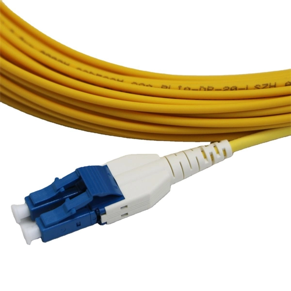
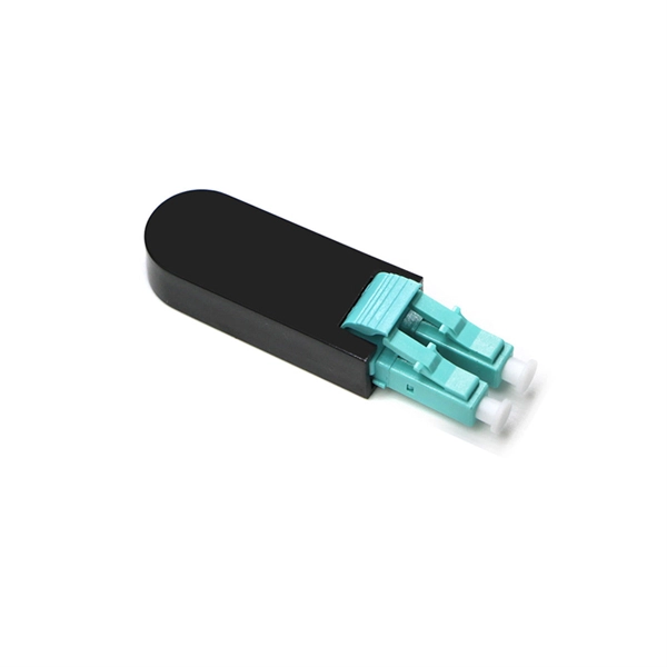
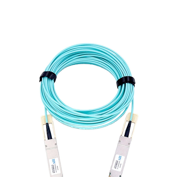
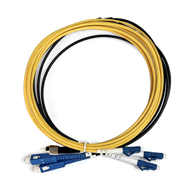
Patch cords, also known as jumper cables or fiber optic jumpers, are short lengths of fiber optic cable used to connect devices within a fiber optic network. They play a crucial role in establishing reliable and high-speed data transmission between equipment such as switches . The fiber optic patch cable must, therefore, be carefully considered. Behind its slender appearance lies the fusion of core types, connector types, and polish levels, each chosen for a specific application. Choosing the right cable thus boils down to educating oneself about fiber optic patch cable. As networks move to higher speeds and higher density, choosing the right fiber optic patch cords becomes critical to the reliability of your system. At ZION Communication, we design and manufacture a full range of fiber patch cords for: This guide will help you quickly understand the main types of. These short fiber optic cords connect transceivers, switches, patch panels, and servers. Without them, even the best optical modules and switches cannot deliver performance. In today's high-speed data transmission era, fiber optic patch cords have become essential components in telecommunication networks, data centers, and enterprise cabling systems.
[PDF]
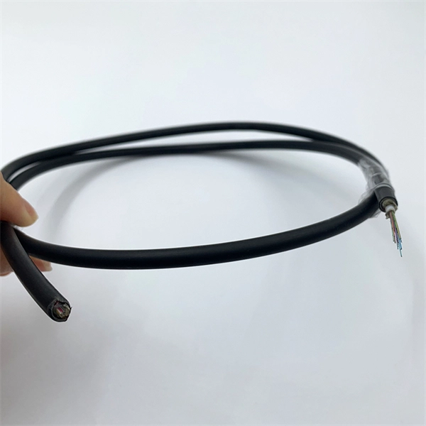
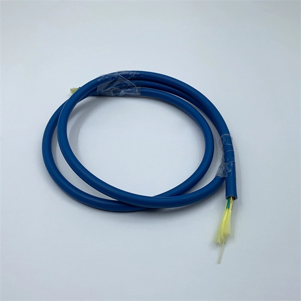
Stranded fiber optic cable is a loose tube made of high-modulus plastic by adding colored optical fiber and ointment at the same time, and the optical fiber can move in the tube. Different loose tubes are twisted along the central reinforcing core to make the cable core. A TOSLINK optical fiber cable with a clear jacket. These cables are used mainly for digital audio connections between devices. The cable core is added. A steel messenger is a stranded steel cable that acts lashing wire. This document describes further details of messenger strand, lashing wire, and the planning and installation process. Steel messenger strand consists. Fiber optic cables are used to transmit data and audio signals using light. They come in different types, each designed for specific applications and distances. This guide will help you identify the most common types of fiber optic cables and understand how many strands of fiber are typically found. Unlike copper wires, which are limited by lower data transmission speeds, shorter transmission distances, and higher susceptibility to electromagnetic interference, fiber optic cables offer unparalleled performance and can cover much greater distances without bumping up against signal degradation. Fiber optic "cable" refers to the complete assembly of fibers, other internal parts like buffer tubes, ripcords, stiffeners, strength members all included inside an outer protective covering called the jacket.
[PDF]
The FOA is an international non-profit educational association that is chartered to promote professionalism in fiber optics through education, certification and standards. FOA is also an internationally recognized certifying body for fiber optics. The May 2026 FOA Newsletter is now. Fibre optics and optical communications is the use of thin strands of glass for sending information encoded into light over long distances. FOA has more than a quarter-century of experience in developing the fiber optic workforce around the world. The FOA was founded in 1995 by a group of trainers from industry, government and education who wanted to create industry standards for training and certifying fiber optic technicians. Founded in 1995 by a dozen prominent fiber optics trainers and industry personnel. As of the end of 2018, about. Corning is opening three new advanced manufacturing plants in the U. dedicated entirely to optical technologies for Nvidia. The partnership brings together two of the infrastructure companies benefiting the most from the artificial intelligence boom. Corning shares are up more than 250% in the.
[PDF]
A fiber optic transceiver (also called an optical transceiver) is a compact module that both transmits and receives data signals through optical fibers. It serves a dual purpose — transmitting electrical signals as light pulses and receiving light pulses to convert them back into. Fiber optic communication systems use light pulses to transmit information over long distances via optical fibers. These systems rely on three vital components working together – the communication channel, the optical transmitter, and the optical receiver. The optical fiber cable itself makes up. They consist of a transmitter on one end of a fiber and a receiver on the other end. Most systems operate by transmitting in one direction on one fiber and in the reverse direction on another fiber for full duplex operation. Most systems use a "transceiver" which includes both transmission and. A fiber optic cable consists of five basic components: the core, the cladding, the coating, the strengthening fibers, and the cable jacket. Fiber optics deals with study of propagation of light through transparent dielectric wageguides. The fiber optics are used for transmission of data from point to point location. Such fibers are widely used in fiber-optic communication, where they permit transmission over longer distances and at higher bandwidths (data transfer rates) than.
[PDF]
Single mode and multimode fiber optic cables are two different types of fiber optic cable aimed at different use cases. Single mode cables are typically made with a single strand of glass at their core, leading to a n.
[PDF]
This section provides an overview for fiber optic sensors as well as their applications and principles. Also, please take a look at the list of 18 fiber optic sensor manufacturers and their company ranki.
[PDF]
At a fundamental level, a fiber optic coupler is a device that distributes or combines optical signals (light) between two or more optical fibers. In simple terms, they serve as the 'traffic managers' of the light that carries information within the fiber optic network. A fiber optic pigtail is actually the end of a fiber optic cable with fiber optic connectors on both sides of the cable only, leaving no connectors on the other side so that the connector side can come from the device and the other side can be fused together with the fibers of the optical cable. The working principle of. A coupler can be used as a splitter to couple out some portion of the light circulating in the resonator of fiber laser, for example. Directional 2 × 2 couplers (see Figure 1) are usually used for such purposes. It functions by dividing a single incoming light path into multiple outgoing paths, or by combining light from several input paths into a single output fiber. This capability is fundamental. Couplers are mainly used for fiber optic wiring, fiber optic equipment connection and other occasions. Inspirational to provide you with the highest quality products. Adapter insertion loss is typically 0.
[PDF]
Instead of fusing one fiber at a time, mass fusion splicing can fuse up to all 12 fibers in one ribbon at once. Many of today's cables with high fiber count involve subunits of 12 fibers each that can be quickly ribbonized. Fiber optic joints or terminations are made two ways: 1) splices which create a permanent joint between the two fibers or 2) connectors that mate two fibers to create a temporary joint and/or connect the fiber to a piece of network gear. Either joining method must have three primary characteristics. Fiber optic splicing is the process of seamlessly joining two single Splicing has a lower optical loss and back-reflection than other terminations, making it the ideal choice for maintaining signal integrity and reliability in fiber optic networks. There are numerous use cases for fiber optic splicing. Through splicing, fiber optic technicians can extend the length of the fiber to make it long enough for use in a required cable run. As. To begin, the standard definition of splicing in optical fiber is joining two fiber optic cables together. The other, more common, method of joining fibers is called termination or connectorization. Splicing is most commonly used in the field but has application in cable assembly houses.
[PDF]
Google has announced Dhivaru, a new Trans-Indian Ocean subsea cable system that will connect the Maldives, Christmas Island and Oman. This investment will build on the Australia Connect initiative, furthering the reach, reliability, and resilience of digital connectivity across the Indian Ocean. The project expands the company's Australia Connect initiative and aims to improve regional reach, reliability and resilience at a time of rapid global growth in. President Dr Mohamed Muizzu has welcomed Google's decision to invest in a new international submarine cable landing station and network facility in Hithadhoo, Addu City, describing it as a strong signal of global confidence in the Maldives' stable, transparent, and investor-friendly environment. The initiative forms part of the company's broader Australia Connect programme, aimed at.
[PDF]