Different solar panels will have information on the sticker on the back showing how to test. (1) Using a voltage meter, locate the open-circuit voltage (Voc) on the specifications label on the back of your solar panel. Write it down for late. Different solar panels will have information on the sticker on the back showing how to test. (1) Using a voltage meter, locate the open-circuit voltage (Voc) on the specifications label on the back of your solar panel. Write it down for later use. To measure the voltage of a DC circuit, you should prepare your multimeter by plugging the black probe. The short circuit current (Isc) on a circuit panel is located on the specifications label on the back of the panel. Record this number for later use. To prepare your multimeter to measure amps, move the red probe to the amperage terminal and set your multimeter to the amp setting (A). If your multimeter is not automatic-ranging, be sure to choose t. You can also measure the voltage of a photovoltaic panel (PV Current) by connecting it to a charge controller. It's possible to use a multimeter to determine how much current your solar panel is outputting, but you'll need an extra piece of equipment first. 1. Solar charge controller 2. Battery Plug the solar charge controller into the battery. Con.
[PDF]

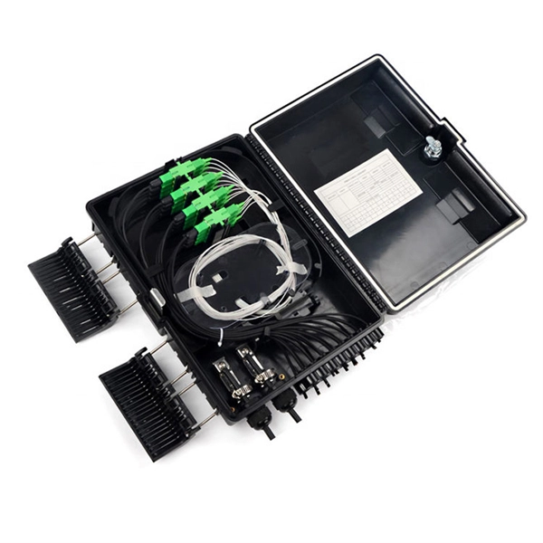
In this video, we'll walk you through the process of wiring a home distribution box with a detailed connection diagram. Whether you're an electrician or a DIY enthusiast, this guide will help you understand the basics of home electrical distribution. more Welcome to our channel! In this video. Understanding the wiring diagram of an electrical panel box is essential for electricians and homeowners alike, as it allows them to troubleshoot any electrical issues, carry out repairs, or make additions to the system. The electrical panel box wiring diagram provides a visual representation of. A distribution board or distribution box is where the main power supply is distributed to multiple loads. And all the switching and protective devices are installed in the distribution box. Single Phase Distribution Box generally consists of Double Pole MCBs, Single Pole MCBs, and RCCBs. Connect the two hot conductors (typically black and red) to the line terminals of the main disconnect switch. Tighten each lug to 250 inch-pounds using a torque wrench. What is Distribution Board? Distribution board.
[PDF]
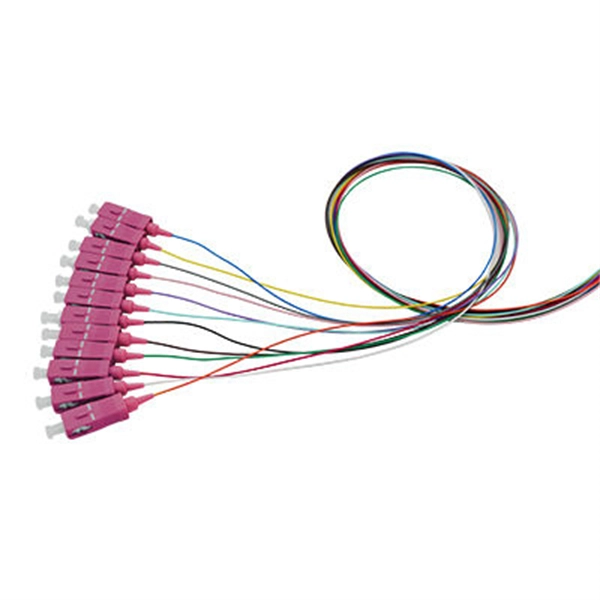
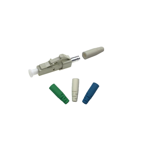
A ferrule puller tool is a specially engineered hand tool designed to extract ferrules from tubing, pipe fittings, and compression joints. The CK01, CK03, and CK05 Fiber Optic Termination / Connectorization Kits include all the necessary tools and supplies to install connectors on single mode and multimode optical fiber. All that's needed to create a fiber optic patch cable is the optical fiber and appropriate connectors. Our termination kits, for example, are equipped with all of the necessary tools — pin and socket polishing tools, jacket strippers. post polishing failures. The document is intended to inform and educate about polishing processes and commercial automated polishing equipment with various fixturing in order to achieve a stable low insertion loss, targeted return loss, acceptable 3D endface geometry, and defect free visual fiber. The ratchet in these crimpers applies the right amount of pressure to ensure a complete crimp in wire ferrules every time. Fixed Crimping Slot— Crimpers with a fixed crimping slot have separate slots for each wire gauge. Read more: How Do I Know Which Crimping Tool To Use? What are Cable Ferrule Crimping Tools? Cable ferrule crimping tools are tools or machines. The Stainless Burner has two ceramic combustion tubes, which require periodic replacement: an inner and an outer tube. Tools • 1 - 1/4” Open End Wrench • 1 - 3/8” Open End Wrench • 2 - 7/16” Open End.
[PDF]
National Electrical Code (NEC) allows up to three grounding conductors to terminate under one lug on a grounding bus, provided it is listed for such use. This is covered under section 110. Correct grounding of services depends upon understanding the definition and role of the grounded conductor. The neutral conductor is typically the grounded conductor connected to the system's neutral point, carrying current under normal operation. Grounding electrode conductors must be connected at. Sometimes if I have a 3 or 4-gang plastic nail-on switch box that has a bunch of NM cables, when I'm making up the box rather than using a big blue wire-nut for my grounds I'll separate the grounds into 2 groups and use red/tan wirenuts instead, especially if there's 2 circuits in the box. This configuration may not comply with current electrical. Learn how to connect equipment grounding conductors to receptacles and keep their continuity in boxes. The basic rule achieves this through an equipment grounding jumper; four exceptions. A grounding terminal or grounding-type device on a receptacle, cord connector, or attachment plug may not be used for purposes other than grounding. (b) Branch circuits — (1) Identification of multiwire branch circuits. When conductors are spliced inside a box or terminated to.
[PDF]